The Engineer Tutor
Learn from our Experience


Before I get started on this post I just thought I would give you some background on why I did this particular project. I worked at Control4 for a time and they had a hardware lab with various pieces of equipment. There were some hot air rework stations along with oscilloscopes and other equipment. But, they had a binary clock on one of the shelves. I later worked at L3 and there was a fellow there with you guessed it a binary clock. I have been fascinated by these and thought I should buy one. But, later thought I should make one. I have been playing with the Blue Bird boards and thought that would be a fantastic platform to build my clock on. So I started.
Now what do I need. I need LEDs, lots of LEDs. I purchased some blue 0805 LEDs from China and had a bunch of them. I thought blue was a good color and decided to use those. Now for how to drive the LEDs. I could use the processor but that would take a lot of the pins of the processor to do that. I could multiplex the LEDs but then I thought of the MCP23017 I had laying around. That would be perfect, it only takes 2 pins to drive it as it has an I2C interface. It has 16 I/O lines which would be plenty to drive the LEDs of the clock without multiplexing or anything complicated. So, I set out on my binary clock adventure.
The MCP23017 has the same foot print as the processor. So, no foot print to make for that. The 0805 LEDs have the same foot print as all the 0805 caps and resistors I have so, nothing to be done for that. I did need to modify the 0805 foot print I have a bit to show the direction for the LED installation. So, there was one change to that. I proceeded to work on the schematic.
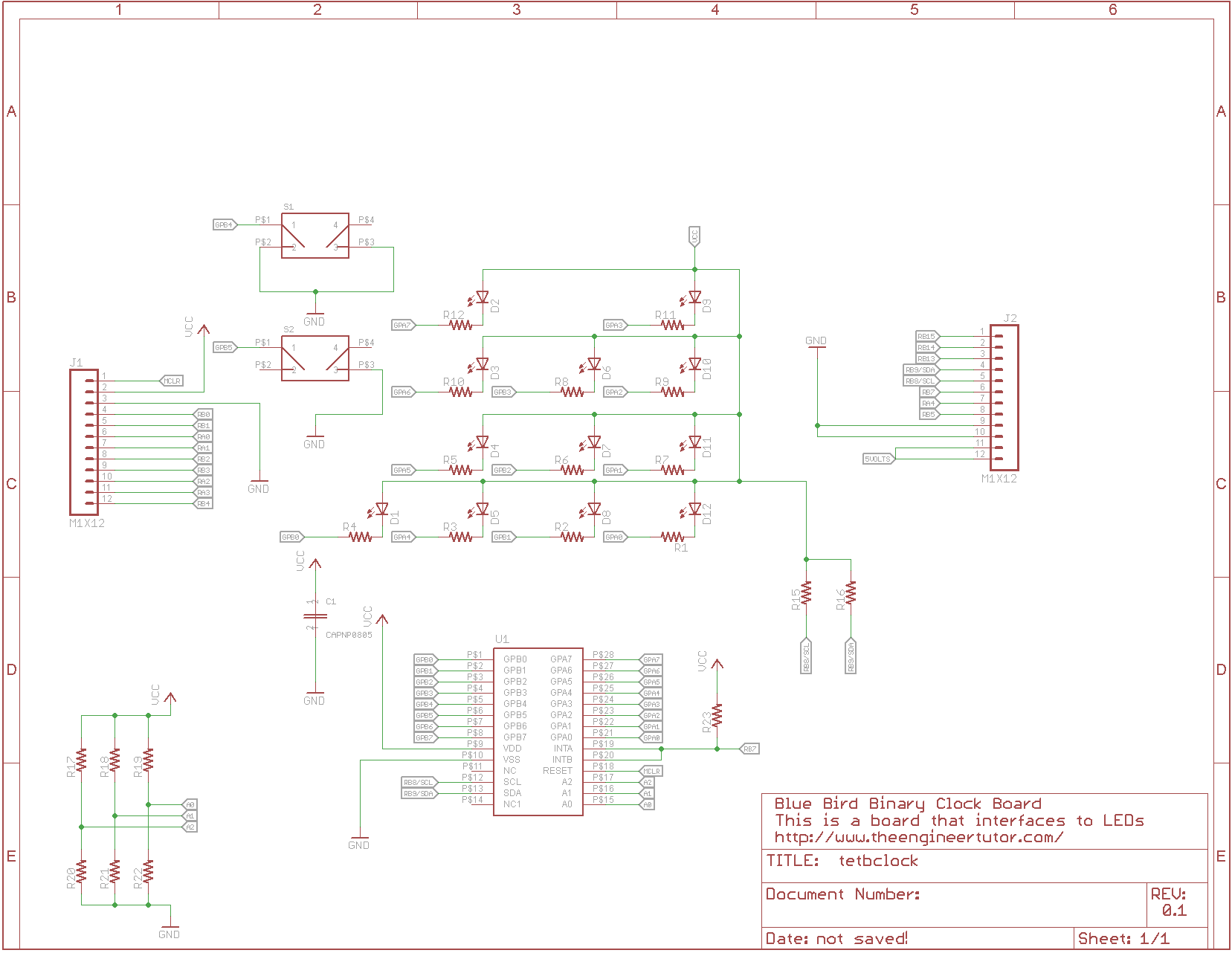
With all the parts chosen and in stock I started laying parts down on the schematic and hooking them up. I wanted to drive the LEDs with an active low on the MCP23017. It can sync more current than it can source so, that is the way I hooked up the LED’s. You can see that from the schematic. Once the parts were all on the schematic then it came time to layout the board. It was pretty smooth. I couldn’t do much movement on the LED’s to help the layout as I wanted them in specific positions on the board. After a little bit of work I got all the traces and connection on the board without any disconnects or “air wires”.
With the board layed out I sent it off to OSH Park for fabrication. I received an email that they upgraded me to their faster service for free. How sweet is that! I few days later I received my binary clock board. It was a Saturday (I love getting new boards on Saturday). So, I set right to work building one up. The LEDs were a little bother some as they were close together along with their current limiting resistor. But, I finally got all the LEDs on the board along with all the other necessary parts. I checked VCC to GND resistance to make sure the rails weren’t shorted together and pushed it on top of a Blue Bird board.
Now the moment of truth, could I talk to the board. I wrote some software to drive the I2C port and talk to the binary clock. Nothing, absolutely nothing from the binary clock. I hooked up my logic analyzer to check the I2C bus and see what was going on. I could see the initialization of the I2C bus but, it just stayed low never doing any toggling??? What was going on. I pulled the binary clock and put in my EEPROM/temperature board to make sure the processor could talk I2C. That worked great!! So, what was the problem. I tried a few things like single stepping through the I2C init routine trying to see a problem with the code but there just wasn’t any problem with it. I went to the schematics to see if I could figure anything out. The schematic looked good. I then started looking at the layout of the board. I looked at the pull up resistors and I found it. There was no connection between the pull up resistors and VCC. How could this happen? I looked at the schematic and according to the schematic there should be a connection. I grabbed the VCC label that was attached to the pull up resistors and moved it. Then I saw it. There was no connection between the label and the line. Oh man, how could eagle do this to me. According to the schematic there wasn’t a connection but it sure looked like there was a connection. I thought how can I fix this. Then it dawned on me I could put in an EEPROM/temperature board which would provide pullups for the I2C bus. I did that and wow, I was able to talk to the binary clock.
Now that I was talking to the binary clock it was time to get serious about writing code to drive the binary clock. I thought I would use a simple delay to keep track of seconds. When each second expired I would increment the number of seconds that had accumulated and when it reached 60 I would bump the minutes and when the minutes reached 60 I would bump the hour and when the hour reached 13 I would set it to 1. I was only doing a 12 hour clock. It is a minimalist binary clock. I wanted to use the minimum number of LEDs that I could. I added two switches to set the time. One button would increment the minutes and one would increment the hour. With these two buttons I’m able to set the time. There is no battery back up so each time it is plugged in you have to set the time. I’m thinking that I could use a DS1337 with a coin cell to maintain time when there is no power. The DS1337 runs on 3 volts which is what the Blue Bird Board runs. I’m going to leave that for another project. I have my binary clock, now to learn how to tell time in binary. Have fun and build something exciting.
Blue Bird Board Binary Clock
Here is the code for the binary clock. You will need the library to get this to work. You can get the library here.
#include "./USB/usb.h"
#include "./USB/usb_function_cdc.h"

#include "HardwareProfile.h"
#include "rtos.h"
#include "pins.h"
#include "initializeSystem.h"
#include "masterI2C.h"

extern int numBytesRead;         // USB variable
extern char USB_In_Buffer[256];  // USB in buffer
extern char USB_Out_Buffer[64];  // USB out buffer
extern unsigned char NextUSBOut; // USB number of bytes to write

/** CONFIGURATION **************************************************/
_CONFIG1(JTAGEN_OFF & GCP_OFF & GWRP_OFF & ICS_PGx1 & FWDTEN_OFF & WINDIS_OFF & FWPSA_PR32 & WDTPS_PS8192)
_CONFIG2(IESO_OFF & FNOSC_FRCPLL & OSCIOFNC_ON & POSCMOD_NONE & PLL96MHZ_ON & PLLDIV_DIV2 & FCKSM_CSDCMD & IOL1WAY_OFF)
_CONFIG3(WPFP_WPFP0 & SOSCSEL_IO & WUTSEL_FST & WPDIS_WPDIS & WPCFG_WPCFGDIS & WPEND_WPENDMEM)
_CONFIG4(DSWDTPS_DSWDTPS3 & DSWDTOSC_LPRC & RTCOSC_LPRC & DSBOREN_OFF & DSWDTEN_OFF)

#define WRITE 0
#define READ 1
#define OUTLEN 32
#define IOADD 0x20
int charToSend;
unsigned char add[2];
unsigned char add1[2];
unsigned char add2[2];
char outstr[OUTLEN];
unsigned char str[4];
unsigned char str1[4];
unsigned char str2[4];
unsigned char error;
int seconds = 0;
int minutes = 0;
int hours = 1;

void handUSB(void);

unsigned char dispstr[2];
unsigned char dispadd[1];

int state = 0;
int keyState = 0;

// This routine is run when a transaction with the I2C bus is finished
void
getVal(void)
{
  if (error)
  {
    snprintf(USB_Out_Buffer,64,"Couldn't find device\r\n");
  }
  snprintf(USB_Out_Buffer,64,"0x%02X\n",str[0]);
  NextUSBOut = strlen(USB_Out_Buffer);
}

// This routine simply displays the time on the LEDs
void
displayNewTime(void)
{
  dispadd[0] = 0x12;
  dispstr[0] = ~((hours<<4) | (minutes&0x0F));
  dispstr[1] = ~((minutes&0xf0) >> 3);
  i2cQueue(WRITE,IOADD,dispadd,1,(unsigned char *)dispstr,2,&error,getVal);
}

// Handle the USB here
void
handUSB(void)
{
   if (numBytesRead > 0)
   {
     charToSend = USB_In_Buffer[0];
     sprintf(USB_Out_Buffer,"Got Char 0x%02X\r\n",charToSend);
     NextUSBOut = strlen(USB_Out_Buffer);
     numBytesRead = 0;
   }
   queueUSB(handUSB);
}

// This routine looks at the buttons for presses and if
// it detects a button press it increments the minute or hour
// and displays the new time
void
reRead(void)
{

  add[0] = 0x13;

  //str[0] = ~(1 << state);
  //str[1] = ~(1 << state);
  i2cQueue(READ,IOADD,add,1,(unsigned char *)str,1,&error,getVal);
  str[0] = ~str[0];
  str[0] &= 0x30;
  switch (state)
  {
    case 0:
      if (str[0])
      {
        // we have a switch
        keyState = str[0];
        state = 1;
      }
      break;
    case 1:
      if (str[0])
      {
        if (keyState == str[0])
        {
          if ((keyState) & 0x10)
          {
            hours++;
            if (hours > 12)
              hours = 1;
          }
          if ((keyState) & 0x20)
          {
            minutes++;
            if (minutes > 59)
              minutes = 0;
          }
          displayNewTime();
        }
        state = 2;
      }
      else
      {
        state = 0;
      }
      break;
    case 2:
      if (str[0])
      {
      }
      else
      {
        state = 3;
      }
      break;
    case 3:
      if (str[0] == 0)
      {
        state = 0;
        keyState = 0;
      }
      else
      {
        state = 2;
      }
      break;
  }

  while (!delayMS(reRead,50))
    runNext();
}

// Here we increment the seconds each second
// and minutes and hours if needed
void
incSeconds(void)
{
  seconds++;
  if (seconds == 60)
  {
    seconds = 0;
    minutes++;
    if (minutes == 60)
    {
        minutes = 0;
        hours++;
        if (hours == 13)
          hours = 1;
    }
    displayNewTime();
  }
  while (!delayMS(incSeconds,1000))
    runNext();
}

/******************************************************************************
 * Function:        void main(void)
 *
 * PreCondition:    None
 *
 * Input:           None
 *
 * Output:          None
 *
 * Side Effects:    None
 *
 * Overview:        Main program entry point.
 *
 * Note:            None
 *****************************************************************************/
int main(void)
{
  initializeSystem();
  // TODO need to fix these names not good.  They are too close.
  InitializeSystem();

  i2cInit(SPEED100K);

  // setup the MCP23017
  // setup the output values
  add[0] = 0x12;
  str[0] = 0x00;    // a value
  str[1] = 0x00;    // b value
  i2cQueue(WRITE,IOADD,add,1,(unsigned char *)str,2,&error,getVal);

  // here we setup the direction of the I/O lines
  add2[0] = 0;
  str2[0] = 0x00;   // a dir
  str2[1] = 0xF0;   // b dir
  i2cQueue(WRITE,IOADD,add2,1,(unsigned char *)str2,2,&error,getVal);

  // Add a couple of pull ups for the buttons
  add1[0] = 0x0D;
  str1[0] = 0x30;    // pull ups b4 b5
  i2cQueue(WRITE,IOADD,add1,1,(unsigned char *)str1,1,&error,getVal);

  queueUSB(handUSB);

  // default time.  Not really usefull in fact a different time might
  // be a good idea.
  hours = 10;
  minutes = 58;
  displayNewTime();

  while (!delayMS(reRead,50))
    runNext();

  while (!delayMS(incSeconds,1000))
    runNext();

  while(1)
  {
    runNext();
  }//end while

}//end main