The Engineer Tutor
Learn from our Experience


I have been working on a batch of Blue Bird boards. They are prototypes which I thought might make a good test run for building lots of boards at one time. I stacked together 6 boards and started working on them. I was able to complete all 6 boards without connectors in about 40 minutes. I tried to build them faster but each time I did a group of 6 boards it took me 40 minutes. Oh well, that isn’t bad considering I’m building them by hand.
After completing all 18 boards I started to test them. I was using an oscilloscope to check each pin to make sure it was working and found that very tedious. I needed a test fixture to make testing these a little faster. I started with some perf board and an hour later I had a test fixture with LED’s hooked to each of the I/O lines so that they could be checked out and make sure they are connected properly and working.
With the test fixture I was able to load a test program and test all the boards in about 15 minutes. It really went pretty fast once the test fixture was working. I did find a bad LED which had to be replaced but, after that little issue the test fixture worked great.
When I wired up the LED’s I reversed the LED’s every other line as I was thinking only half would be on at a time which would put less stress on the microcontroller. After I did this I thought darn I should’ve just wired them all the same that way I could run the LED around and written tests to test each LED individually. Right now the test program is turning all the I/O on and all the I/O off. With half the LED’s reversed only half are on at once and the other half are on the next cycle.
The test fixture also has two buttons on it. One for reset and one to put it into boot loader mode. This way I don’t have to have a debug board hooked up to the test fixture. I just put in a processor program it then watch to verify that all the LED’s are flashing. As I went through all the boards I found two of them with cold solder joints around the processor and they needed to be reflowed to take care of the cold solder joints. After doing that the two boards that didn’t work are now working satisfactorly.
The circuit is really easy.

You can see each of the LED’s reversed each line. About half light when the output is high and half light when the output is low.

You can see the pins and the markings I put on the board so I could get the board under test inserted correctly. You can also see the buttons for reset and putting the Blue Bird board into boot load mode.
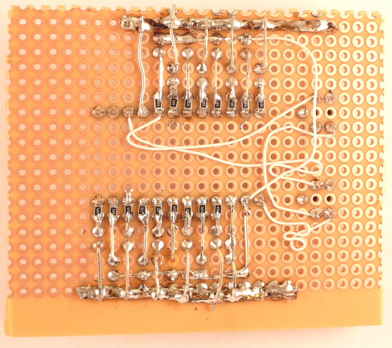
Here is the bottom of the board. You can see that I used surface mount resistors (470 ohm) for the current limiting resistors for the LEDs. You can also see the way I wired the switches. The board works great.