The Engineer Tutor
Learn from our Experience


I have wanted to build a robot for a while. Jameco had a contest where you had to build a robot from a CD. I thought that might be fun, easy, and very inexpensive. I found an old CD and bought some servos to power the robot. Glued the servos to the CD and left it there for a few months. Other things took priority and I didn’t get back to it for a while. Found some time the other day and thought I would finish it up at least get it to the point where it could move around.
As I got to looking at it I realized that it would need a few things. The first thing I would need is a caster for the back end. Looked around on the net and found a ping pong ball caster that I could 3d print. It looked sturdy and I thought it would work. Went looking for a ping pong ball but couldn’t find one, guess I’ll have to order one. Looks like they have seamless ones now. That should be better at rolling as the 3d prints can be a bit rough. This is what I had in mind.
While waiting for my ping pong balls I thought I would start on the ultrasonic range finder. These little gems can sense objects in front of the robot. I thought it would be a good sensor to have. Make the robot look a little more intelligent rather than just running into walls. The range finder runs on 5 volts where as the Blue Bird board is a 3.3 volt design. It does have 5 volts coming from the board and there are a few 5 volt tolerant pins I can use on the processor. With this I set out to hook up the range finder.
The range finder has an input and an output pins. The input pin is used to tell the range finder when to send out a pulse. When the input pin is set high the output pin of the range finder goes high also and a 40khz pulse is sent out. The range finder waits for a return pulse and when it receives the pulse it sets its output pin low. The processor times the length of time the output pin goes high then low with the length of the high state telling how near or far an object is away. The wave form from the range finder looks like the following:
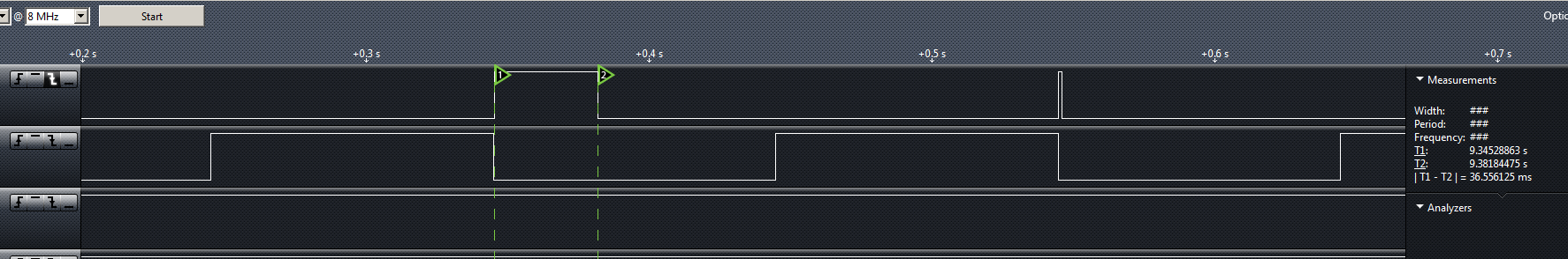
You can see from the wave form that the range finder waits for the input to go high then low which is the bottom active line in the above picture. The top line is the output from the range finder and that shows the distance from the object. One pulse with the two markers is the distance of the top of my bench to my ceiling. The echo took 36.5ms to go from the sensor to the ceiling and back. You can see this if you look to the right in the above picture and see the difference between the two markers. The second pulse is the distance from my hand to the sensor. You can see that my hand was really close and the ceiling was further away by the length of the pulses from the output of the range finder. With these times you can actually calculate the distance the object is away. The smaller the pulse the closer the object.
I had some issues with the input change interrupt. I have used this feature of a PIC processor before with great success. I implemented a custom serial protocol that had a 36 bit word in it. So I was no stranger to the feature but, I couldn’t get it to work. My problem was I was enabling the wrong change interrupt line. As soon as I moved it to the correct one it all started to work. I had to change the input prescale to the counter as it was overflowing when the distance became large and would register as a close object rather than an object far away. I got the prescale set right and was getting some good range number from the processor. I used the change interrupt to detect with the range finder output was high then I started the timer then when the ranger finder’s output went low I would read the timer and save the value for future reference which was shortly.
With the time it takes the sound to bounce back to the sensor we can now calculate the distance to the object. The speed of sound is 343.59 meters per second (1127 ft/s). We just have to take the round trip time of the pulse the range finder sends out multiply that by the speed of sound and divide that by 2 to get the distance to the object. The way I have my timer setup is with an input of 16000000 counts per second with a prescale setting of 64 so the number of ticks per second going to my counter is 250000. So, each tick represents .000004 of a second which is 4 microseconds. If we receive a count of 231 counts to calculate the distance we would perform the following calculation:
((231 * .000004) * 343.59) / 2 = .1587 meters which is for us in the US is about 6 inches. To perform the calculation directly in feet do the following:
((231 * .000004) * 1127) / 2 = .52 feet which is about 6 inches (6.248 inches to be precise).
Very easy to calculate the distance to the object. It is easier to use floating point but you could use a fixed point representation if you wanted to use integers and not load the floating point library. Fixed point math is a whole discussion by itself.
NOTE: the speed of sound varies depending on your altitude, temperature, and humidity. But for our purposes the above figures are good for sea level.
Fixed Point Distance Calculation
To do the above calculation using fixed point math isn’t difficult. You just have to keep track of the decimal point and put the decimal point back into the result when you are done. To take our above example we would have the following:
231 * 4 = 924 (Remember this is actually .000924 this is where the decimal place is)
1127 * 924 = 1041348 (The decimal place is here 1.041348)
1041348 / 2 = 520674 (The decimal place is here .520674)
12 * 520674 = 6248088 (The decimal place is here 6.248088)
So, we have 6.248 inches of distance. To print this out on say an LCD display you would do the following:
6248088/1000000 = 6 This is the integer portion of the inches which you would put on the display followed by a decimal point. Next you would do:
6248088%1000000 = 248088 This is the fractional part of the inches which you would put on the display following the decimal point. Note the difference in the operators. One is divide and the other is modulus. Divide gives you the number of times the bottom number will go into the top number and modulus gives you the remainder which is perfect for our fixed point calculation. The key is keeping track of the decimal point!!!
NOTE: you have to use 32 bit integers to get the precision I’m using here. A 32 bit integer can handle 9 decimal digits. If you want to do unsigned integers it can handle 10. There are some tricks you can do so you can keep the number of digits to a minimum and that is do the divide by 2 earlier so the numbers don’t get so big.
There you have it in a nut shell very easy sensor to work with.