The Engineer Tutor
Learn from our Experience


Build of materials for the blink LED tutorial:
1.) Pickit3
2.) Breadboard
3.) 1pc. LED
4.) PIC24FJ64GA002
5.) 6 pins Connector
6.) Connecting wires
7.) 1pc. Capacitor 10uf
8.) 1pc. Resistor 330 ohms
9.) 1.pc Resistor 47k ohms
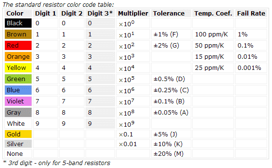
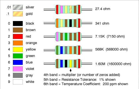
Resistor Color Coding:
After installing those two software packages, MPLAB-X and the compiler we are ready to begin.
Next we need to run MPLAB-X and create a new project.
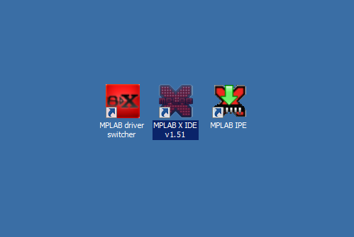
Step 1 – double click the MPLAB X IDE v1.51 icon on your desktop.
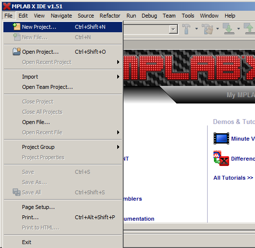
Step 2 – go to file menu then select new project.
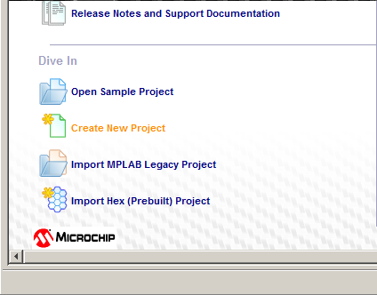
Or at the welcome screen under the dive in, click create a new project.
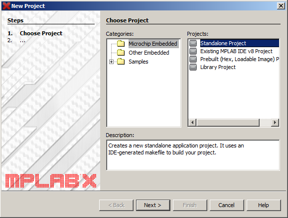
Step 3 – Choose Project – Choose the Microchip Embedded category and Standalone Project, then press the next button.
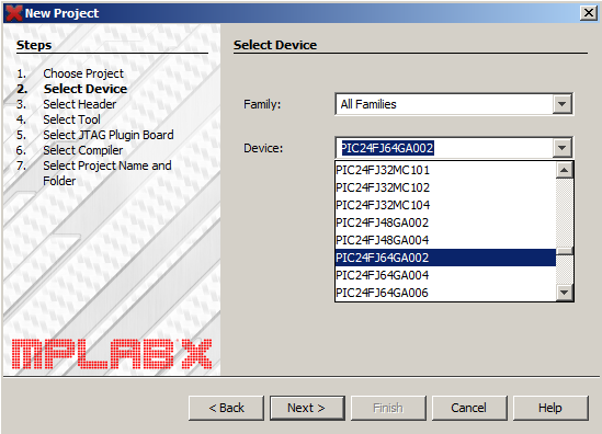
Step 4 – Select Device – Select the PIC24FJ64A002 device, then press the next button.
Step 5 – Select header – Select None Supported Debug Header, then press the next button.

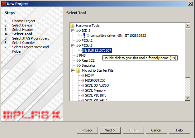
Step 6 – Select Tool – Select SN: BUR121070507 under pickit3, then press the next button. Actually your serial number will be different choose the PICkit3 attached to your system.
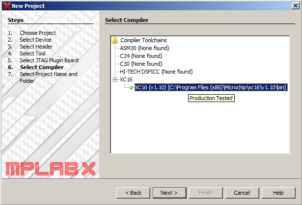
Step 7 – Select Compiler – Select XC16 (v1.10) [C:\Program Files(x86)\Microchip\xc16\v1.10\bin], then press the next button.
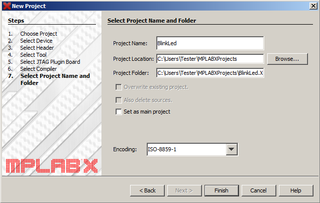
Step 8 – Select Project Name and Folder – Name your project and select project folder, then click the finish button. I just named my project BlinkLed.
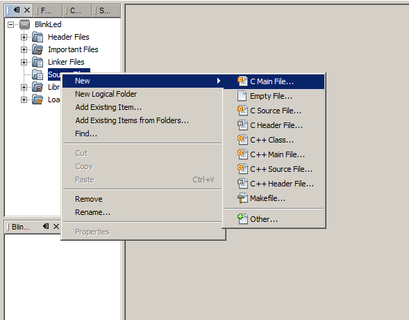
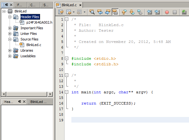
Step 9 – We are done creating the project. Now, on the left sidebar right click the Source Files, New and then select the C Main File.
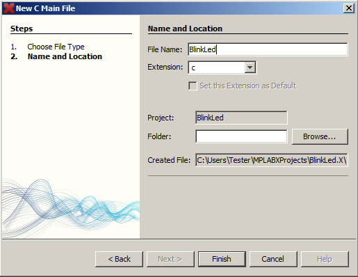
Step 10 – Name and Location – Name the file and choose the location for your C Main file, then click the finish button. I just named the file the same as my project name “BlinkLed”.
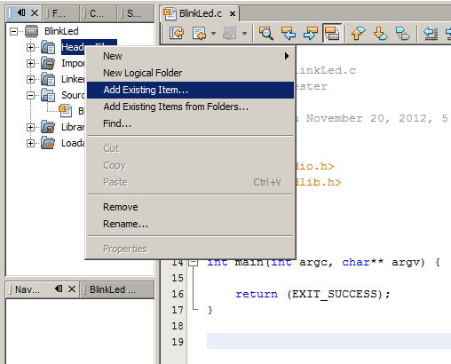
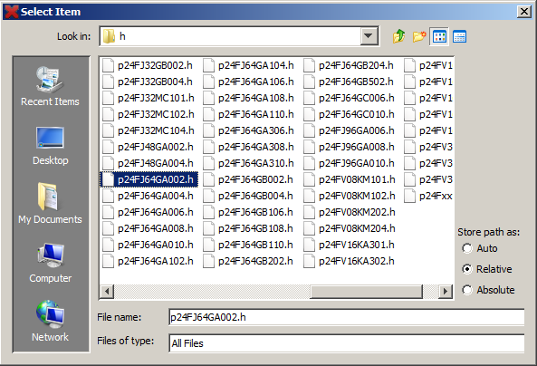
Step 11 – Okay, we are done with the C main File. Now, we need to put a header file in. On the left sidebar right the Header Files, then select Add Existing item. We need to find p24FJ64GA002.h. Here’s the path: c:\Program Files (x86)\Microchip\xc16\v1.10\support\PIC24F\h. If you chose the default location.
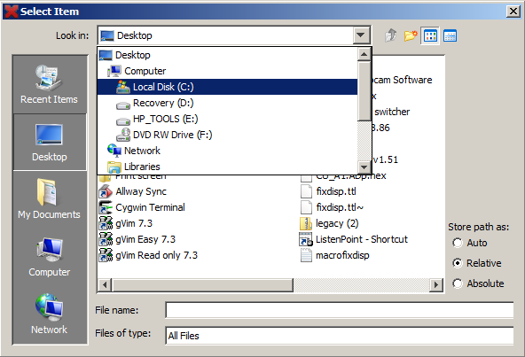
Step 12 – This Select Item Box will appear and Select or go to local disk (C:).
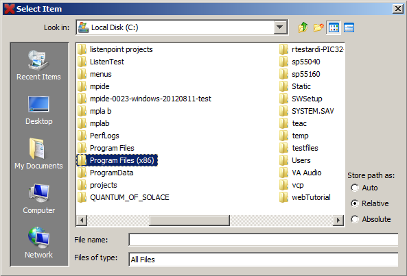
Step 13 – Under local disk (C:), Select or double click the Program Files (x86) folder.
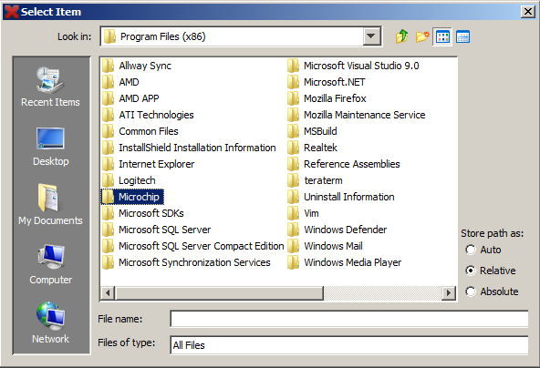
Step 14 – Under Program Files folder, select or double click the Microchip folder.
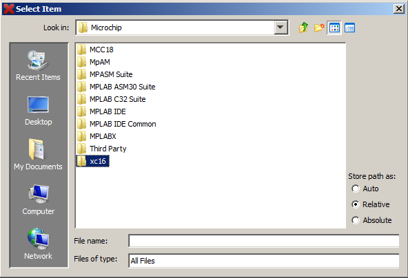
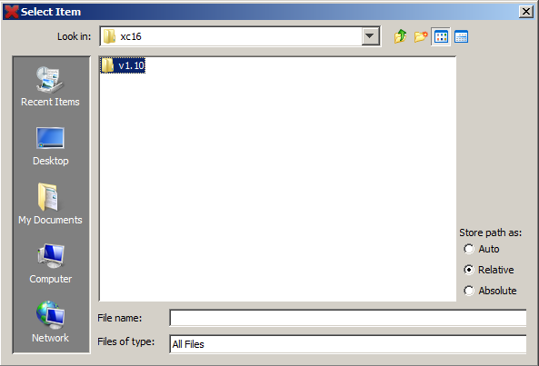
Step 15 – Then, select or double click xc16 folder.
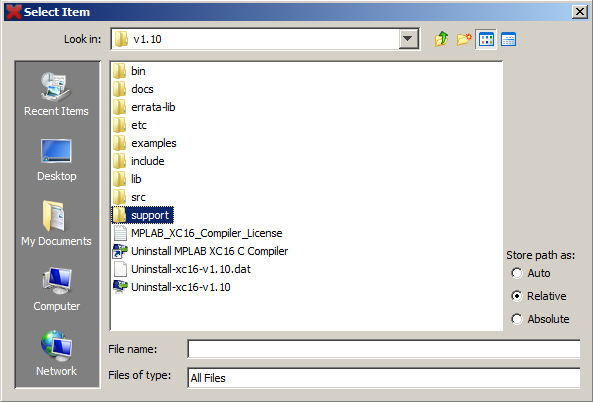
Step 16 – Under xc16 folder, select or double click v1.10 folder.
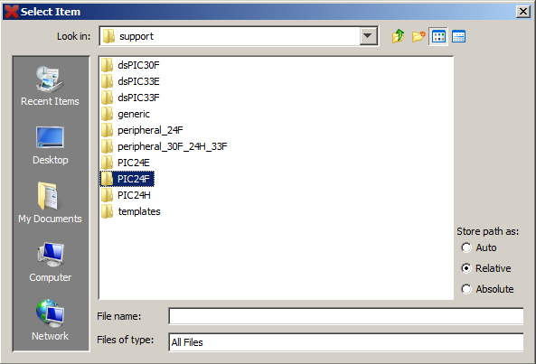
Step 17 – Then, select or double click the support folder.
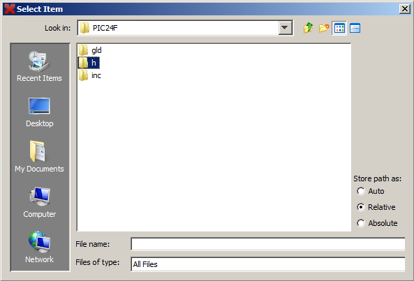
Step 18 – Under support folder, select or double click the PIC24F folder.
Step 19 – Under PIC24F folder, select or double click the h folder.
Step 20 – And under the h folder, select or double click the p24FJ64A002.h.
Step 21 – Now, we already have a Header file. Next, on the BlinkLed.c file, clear all the text or ctrl+A then delete.
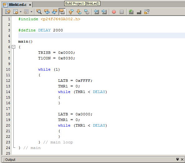
Step 22 – Now enter the following program on the BlinkLed.c file (On white sheet).
#include <p24FJ64GA002.h>
#define DELAY 2000
main()
{
TRISB = 0x0000;
T1CON = 0x8030;
while (1)
{
LATB = 0xFFFF;
TMR1 = 0;
while (TMR1 < DELAY)
{
}
LATB = 0x0000;
TMR1 = 0;
while (TMR1 < DELAY)
{
}
} // main loop
} // main
Step 23 – The contents of the BlinkLed.c now look like this:
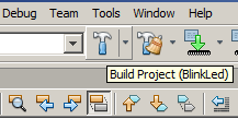
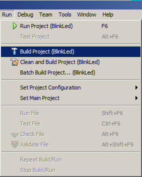
Step 24 – Now, we have two types of mode the release and debug mode. First we go to the release mode. Click only the hammer button on toolbar to build the project for the release mode or select run > Build project from the menu. Wait until the loading is completed.
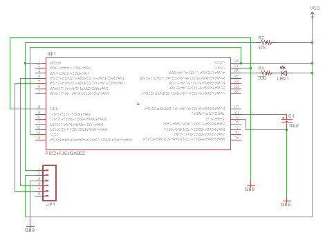
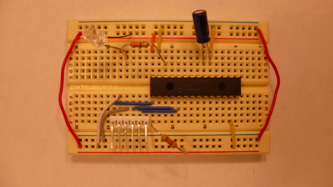
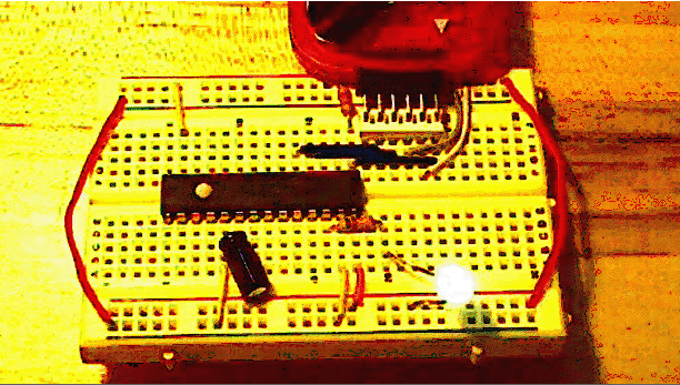
Step 25 – Now you need to wire the device according to the schematic and picture of my breadboard.
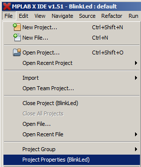
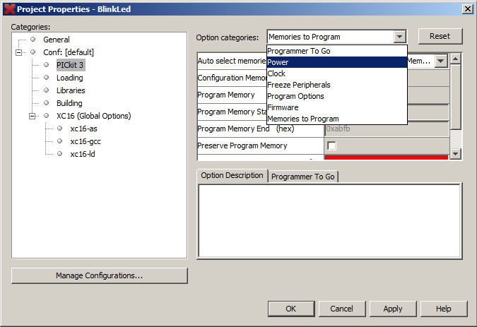
Step 26 – We need to provide power to the processor on the breadboard. To do that, first go to the file menu option and then select Project Properties (project name).
Step 27 – Now select PICkit 3 from the categories and click power for option categories.
Step 28 – Make sure the voltage is set to about 3.250 volts and click the check box next to the Power target circuit from PICkit 3 entry. This should connect you to the device and allow you to program it.
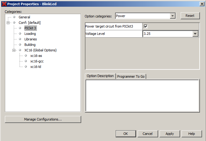
Click the apply button then press Ok.
Step 29 – Now, run the project. Select Run > Run project (project name) from the menu.
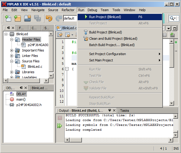
Step 30 – Now, you will see the led blink in release mode. Note, you can’t control the led blink when in release mode.
Step 31 – If you wish to blink the led in debug mode, select or go to Debug > Debug Project (Project name) from the menu.
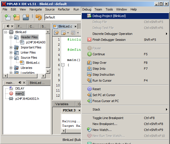
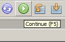
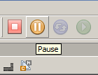
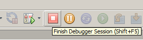
If you programmed it in debug mode you have to hit the green arrow to blink the LED. It should blink as long as you have power to the microcontroller. To pause the led blink, hit the orange circle and to finish the debugger session hit the red box. Also, you can find this button on Debug from the menu.