The Engineer Tutor
Learn from our Experience


In the previous posting we learned how to assign voltages to each pin in a port separately. This posting will improve on that design by introducing a shift register (useful for controlling multiple LEDs).
A note about voltage. I set my PIC to power the circuit with 3.25 V. That way I can simplify my circuit by not having to use voltage restricting resistors to protect my LEDs. Protecting your LEDs with resistors is a good idea, but I just wanted to simplify things for this exercise.
We could map 16 LEDs with the method that we just covered in the previous posting, assigning one pin per LED. What if you want to control more than 16 LEDs? You don’t have enough pins in the PIC. Shift register to the rescue. Simply put, a shift register is an IC that takes in a serial input (one byte at a time) and outputs all bits at once. Basically, with three pins of your PIC you can control 8 LEDs. You can also daisy-chain shift registers and control multiples of 8 LEDs. (We’ll look at daisy-chaining shift registers in part 3.)
You can read more about shift registers here.
The shift register we are going to use is 74HC595, a very common shift register. It is an 8-bit shift register, it has 8 outs. You can buy them here.
Look at the pinout of 74HC595

74HC595 Pinout
Pins 1-7 and 15 are the output pins. Q0 is pin 15, Q1-Q7 are pins 1-7. The other important pins are pin 14 or DS, pin 11 or SH_CP, and pin 12 ST_CP. Those will be connected to our PIC. Let’s see our circuit.
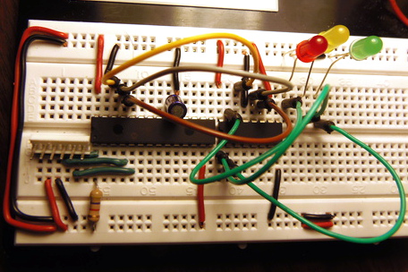
Circuit for Blinkie with a shift register (click to enlarge)
And the schematic:
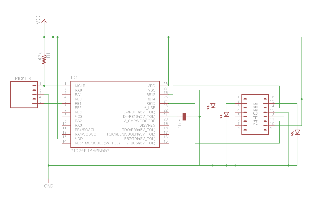
Three LEDs with a shift register schematic
First I connected pins 10 (MR) and 16 (Vcc) to +. Then I enabled output by connecting pin 13 (OE) to -. You could control this from your PIC but I just want it enabled always. I also connected pin 8 (GND) to -.
Then I connected (with three green wires) three outputs to my LEDs. Q0 (pin 15) goes to the red LED, Q1 (pin 1) goes to yellow, and Q2 (pin 2) goes to the green LED.
After that I connected three wires from the PIC to the shift register, so that I can control the shift register. I connected RB15 (pin 26) from the PIC to DS (pin 14) of the shift register (yellow wire). I connected RB14 (pin 25) from the PIC to ST_CP (pin 12) of the shift register. And finally, I connected RB13 (pin 24) from the PIC to SH_CP (pin 11) of the shift register.
The three pins (RB13-RB15) don’t control LEDs directly. They either clock the shift register or latch it to trigger the output. The “patterns” for which LEDs are lit up needs to be a new parameter in our program. Since in our circuit we use only one shift register, and we have max 8 outputs, it is enough to only use eight bits for our patterns.
For example, if we want to light up Q0, we would clock in 1000 0000, or 0x80 to our shift register. To light up Q1, we send 0100 0000, or 0x40. And to light up Q2, we sent 0010 0000, or 0x20 to the shift register.
To light up all LEDs in a pattern we need to:
To simplify things I decided to use functions. That way I can abstract common functionality and make my code cleaner and easier to maintain.
But first, I defined macros to pull pins high or low.
// control the DS
#define DS_low()  LATB &=~0x8000
#define DS_high()  LATB |=0x8000

// control the ST_CP
#define ST_CP_low() LATB &=~0x4000
#define ST_CP_high() LATB |=0x4000

// control the SH_CP
#define SH_CP_low() LATB &=~0x2000
#define SH_CP_high() LATB |=0x2000
Then I defined a macro to check if a bit is set or not in my pattern:
#define CHECK_BIT(var,pos) ((var) & (1<<(pos)))
I will need two functions, one for controlling the shift register (setLEDS) and another to make setting each pattern cleaner (doStep).
So, I created the prototypes first:
void doStep(unsigned int pattern);
void setLEDs(unsigned int pattern);
Then I implemented the functions, following the pseudo code from my “Operating Concept” above, starting with setLEDs.:
void setLEDs(unsigned int pattern) {
    ST_CP_low();
    SH_CP_low();
    int i;
    for (i = 0; i < 8; i++) {
        if (CHECK_BIT(pattern, i))
            DS_high();
        else
            DS_low();

        SH_CP_high();
        SH_CP_low();
    }
    ST_CP_high();
}
It takes in the pattern (0s and 1s for each LED to turn on). Then it clocks the shift register, and finally latches for output.
Then I implemented the doStep helper function to make setting each pattern cleaner.
void doStep(unsigned int pattern) {
    TMR1 = 0;
    setLEDs(pattern);
    while (TMR1 < DELAY) {
    }
}
This method resets the timer, sends the pattern to the setLEDs function, then waits a while.
Finally, my main method that pulls everything together:
int main(int argc, char** argv) {

    TRISB = 0x0000;
    T1CON = 0x8030;

    // reset everything
    LATB = 0x0000;
    doStep(0x00);
    while (1) {
        doStep(0x80);
        doStep(0x40);
        doStep(0x20);
    } // main loop
    return (EXIT_SUCCESS);
}
It sets up the PIC, resets all LEDs, then loops through my patterns, turning on each LED one by one.
Here is the complete listing:
#include <stdio.h>
#include <stdlib.h>
#include <p24FJ64GB002.h>

#define DELAY 4000

#define DS_low()  LATB &=~0x8000
#define DS_high()  LATB |=0x8000

#define ST_CP_low() LATB &=~0x4000
#define ST_CP_high() LATB |=0x4000

#define SH_CP_low() LATB &=~0x2000
#define SH_CP_high() LATB |=0x2000

#define CHECK_BIT(var,pos) ((var) & (1<<(pos)))

void doStep(unsigned int pattern);
void setLEDs(unsigned int pattern);

int main(int argc, char** argv) {

    TRISB = 0x0000;
    T1CON = 0x8030;

    // reset everything
    LATB = 0x0000;
    doStep(0x00);
    while (1) {
        doStep(0x80);
        doStep(0x40);
        doStep(0x20);
    } // main loop
    return (EXIT_SUCCESS);
}

void doStep(unsigned int pattern) {
    TMR1 = 0;
    setLEDs(pattern);
    while (TMR1 < DELAY) {
    }
}

void setLEDs(unsigned int pattern) {
    ST_CP_low();
    SH_CP_low();
    int i;
    for (i = 0; i < 8; i++) {
        if (CHECK_BIT(pattern, i))
            DS_high();
        else
            DS_low();

        SH_CP_high();
        SH_CP_low();
    }
    ST_CP_high();
}
To blink two LEDs, I could loop:
     doStep(0xA0);
     doStep(0x40);
Which first lights red and green, then the yellow in the middle.
Well, that was fun! You learned how to use a shift register to control LEDs.