The Engineer Tutor
Learn from our Experience


For a while now I have been really interested in GPS modules and what they can do. I always thought I would build a very small payload for a balloon and launch it. I have read many accounts of people doing just that. I have an amateur radio license and am very aware of the capabilities of APRS. I have used the APRS system to track my truck and where it is located.
I obtained a couple of very inexpensive GPS modules from China. When I first hooked them up they didn’t seem to work. But, I persisted and was finally able to get them to work. I hooked them up to a bare PIC24FJ64GB002 to begin with. That is where they didn’t work. Not sure why they didn’t work there. I then tried hooking one of the modules up to a Blue Bird Board. When I did that the modules started to respond. I read some where that it could take up to 3 minutes to get a fix from a GPS module. So, maybe I just wasn’t patient enough when I had the module hooked up to just the processor. Also I’m running the module inside my house so there is the structure of the house blocking the signal. That could also be a problem.
With the module working and communicating with the satellites I can see my position and altitude. I can also see the speed of the module which is essentially 0. I have a VW powered dune buggy and thought it would be cool to build a GPS powered speedometer for it. But, that is another project.
There are some things about GPS that are a bit different. The module communicates in what NMEA calls sentences. These sentences start with a ‘$’ and end with a ‘*’ with two digits following the ‘*’ which are the check sum of the sentence. I first started to decode the sentences on the fly but, wasn’t checking the check sum for a valid sentence. I rewrote the decoder to grab an entire sentence check the sum before doing any processing on the sentence.
Once I was decoding the sentences properly I started looking at the different types of sentences and the information I could get from each one. I found a lot of interesting stuff. There is of course the position information but also ground speed in knots. The speed in knots surprised me a bit but, when you realize that the system was first developed for ships it shouldn’t be surprising.
I created a small library to handle the GPS module which attaches to the PIC using a serial port (UART) running at 4800 baud. The baud rate can be changed by sending a command to the module but I chose to leave the baud rate at 4800 baud. This seems to work just fine.
To put the device in a balloon I wanted to use a party balloon. The party balloon doesn’t have a lot of lift so the payload is going to have to be very small and very light. I thought of using a Linx radio module for a first pass at running the balloon and not letting the balloon get very far. One of the problems with the balloons is how to bring it down. A friend of mine said that the balloon shouldn’t be released to come down who knows where, where an animal could be hurt by it. I thought of using a small value resistor to heat up the balloon and melt it to bring the balloon down. I wanted to do a lot of testing with hardware to make sure that the idea is sound and that the balloon could be brought down after say 30 seconds in the air or it travels a certain distance. I wanted to run most of the tests with the balloon tethered so that if there is a malfunction the balloon could be brought down.
Well, enough of my rambling to get a good explanation of the GPS sentences I referred to this site. I also spent some time on this site. The latter site is more complete and I was able to turn on different sentences using the information in the latter site.
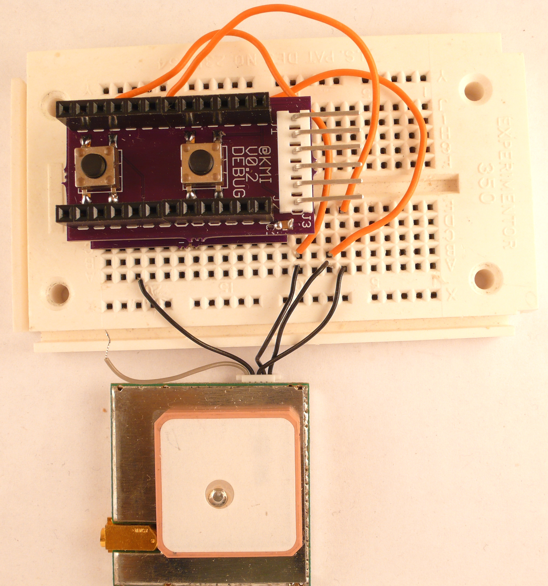
Here is an image of the Blue Bird with a debug board on it including the GPS module. This module didn’t have an identifying marks on it so I’m not sure what it is. I believe most GPS modules work similarly but, get some documentation with your module so you don’t have to guess like I had to on this module.
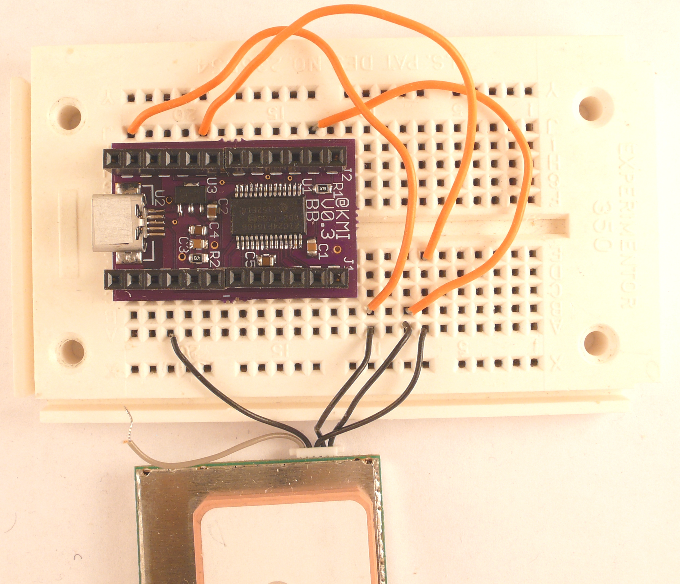
In this picture you can see the Blue Bird board and see a better view of the wiring between the Blue Bird and the GPS module. Just a little explanation on the wiring to this particular module pin 2 on the Blue Bird is 3.3 volts as this module took that voltage one of the few details I knew. Pin 8 is serial TX out of the Blue Bird and pin 12 is the serial RX to the Blue Bird. The final connection is on opposite connector which is ground. So, we have 4 wires to make this work and if you were satisfied with the default configuration of the module you would have to have the TX from the Blue Board hooked up.
The software even checks for a valid check sum from the GPS module. The algorithm for calculating the check sum is very easy. The check sum is the XOR sum of all the bytes between the ‘$’ and the ‘*’ with the two bytes past the ‘*’ is the check sum to compare against. It just takes a simple loop to go through all the bytes doing the XOR to calculate it.