The Engineer Tutor
Learn from our Experience


I have designed a lot of printed circuit boards in my career. I usually use a service to do this but, lately I have had the desire to make my own. I have been doing some research on the net and have found several methods that looked like they might work.
Toner Transfer/Printer
There are two methods that I found. There is the toner transfer method and the photosensitive method. I thought I would try the toner transfer method. I found a site that talked about using OHP (over head projector) transparency laser printer film. His video which shows him using this method was very impressive so I bought the printer he suggested. It is a nice printer and seems to work well.
Laminator
You have to heat the paper that has the toner printed on it while in contact with the copper clad board to get the toner to transfer. I found this site that talks about how to do that. He mentions a Scotch TL901 Laminator so I bought one of these also. I checked my laminator with a temperature probe and found that the one I purchased is reaching 170 degrees C. I didn’t have to modify it all.
Copper Clad Board
I wanted to use the same .032″ board that was shown in the video hoping that I could use a heavy duty paper cutter to cut the board. I tried it but the paper cutter I have isn’t heavy enough to do it. I’m using some metal shears to cut the board.
Etchant and Pulsar paper
I found some very environmentally friendly etchant on Ebay. It is made by Loudwolf Limited and comes in powder form. I have talked to Paul Fullwood of Loudwolf a couple of times and he is very helpful. He mentioned that rather than use OHP film that I should use Pulsar paper. I looked up the Pulsar paper and found that it is designed for toner transfer. I have tried it and it does work.
Printer Settings
I haven’t mastered the multiple passes through the printer to give a good layer of toner on the paper. I’m still having issues getting the print to end up at the same place each time. I do set the printer parameters to the darkest setting and best quality that it has. One other thing that I do and that is panelize the board multiple times so I make the most out of the Pulsar paper. This paper is expensive and multiple passes through the printer I have found causes some issues with the coating on the paper. So, I do one pass with multiple copies of the board on the sheet to fill it out.
Cad Software
I’m using Eagle to design the boards. In my career I have used Protel and that worked well. But, a license to Protel is many thousands of dollars and too expensive for me right now. Eagle is very inexpensive for small boards and they have a hobbyist license that is free.
Tips
I would like to mention that as you design your boards use the polygon fill to leave as much copper on the board as possible. It will etch faster and make your etchant last longer. I have been doing single sided boards and use the polygon fill as a ground plane. That makes it easier to wire the board with ground being every where. You can also heat the etchant to about 120 degrees F which also speeds the etching process.
Here is a board I have been working on. These are the various states the board goes through in the etching process.
Here is the board ready to be etched. You can see that I have touched it up with sharpie marking pen.
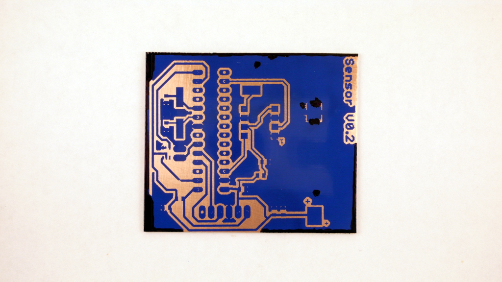
Board Ready to Etch
Here the board has been etched and is ready to have the holes drilled and to be stuffed.
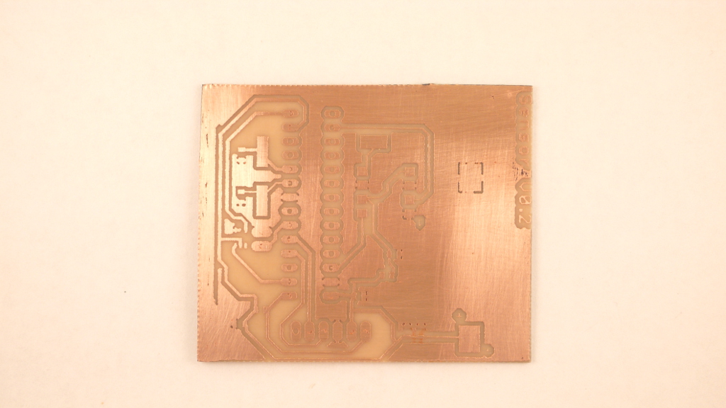
After Etching
Here is the bottom of the board which has been stuffed. You can see the SMD components on this side of the board.
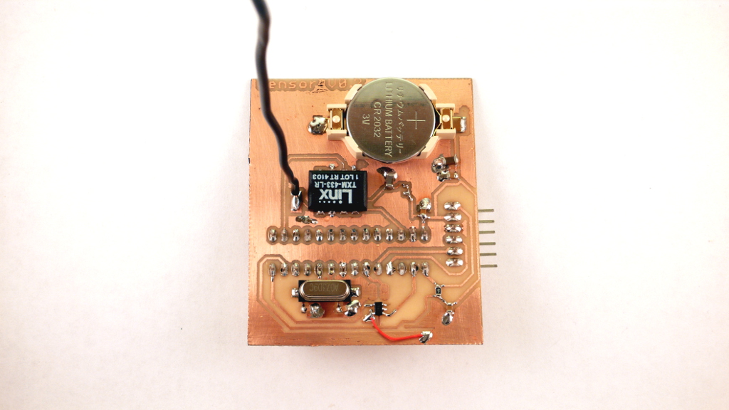
Bottom of Board
Here is the top of the board. You can only see the processor and programming connector. It is a very simple board from this angle. I have been thinking that I should make it entirely SMD. That way all the components will be on one side making the other side nice and smooth for mounting or what ever.
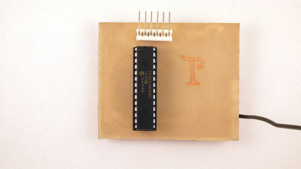
Top of Board