The Engineer Tutor
Learn from our Experience


Servos are so much fun. I use them in my RC airplanes. They help keep my airplane in the air. When I was running glow powered engines they also handled the job of handling the throttle of the engine.
I have found a whole new application for servos. They are great in robotics. They can turn things like range finders to allow the robot to look in different directions. They can also drive the robot if you modify the servo for 360 degree rotation. I have built a couple of servo controlled robots.
I have a Boe-bot chassis. I pulled all the stock electronics from the chassis and put my own board in it. I wanted to build the electronics from scratch and control the servo on my own. As I investigated doing this I found that it was very easy to do. I just had to get the timers setup correctly. Once that was done it was just a matter of tuning the servos so that the robot would travel in a straight line.
Once I had the robot going in a straight line I hooked up an ultrasonic range finder to allow the robot to detect objects in its path. With a little coding I was able to get the robot to avoid these obstacles.
Getting the range finder to work was a trick. It requires you to send a pulse and then measure the time it takes for the pulse to come back. I use a timer to measure this time. If the time is short I assume that there is an object in front of the robot. If the time is long or very long I assume the path is clear ahead and full speed forward.
There are other ways to detect objects. You can use infrared emitters and detectors for this job also.
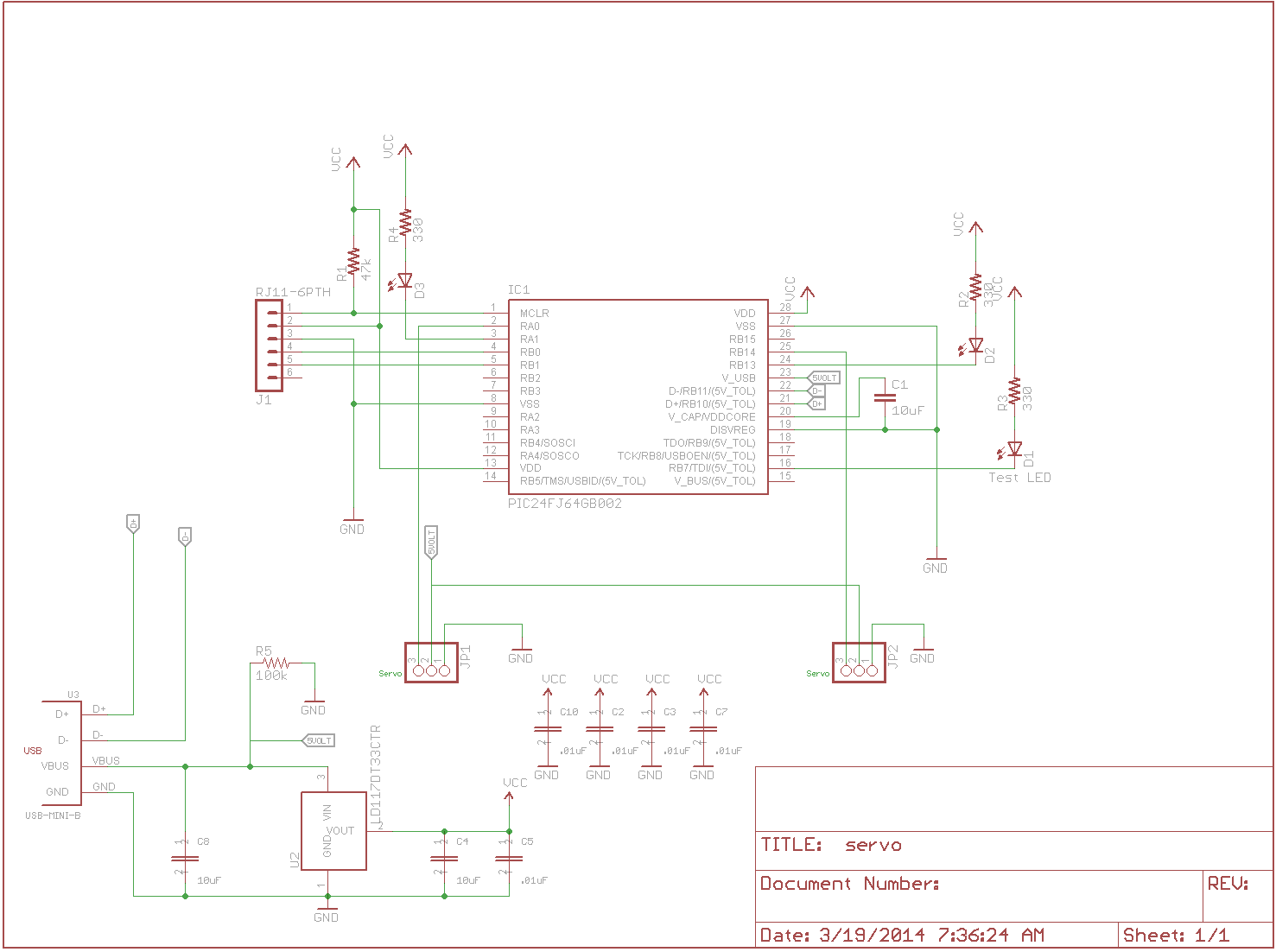
Servo Schematic
You can see two servo connectors in this schematic. The servo’s require about 5 volts to run. The rest of the system requires 3.3 volts to run. This is accomplished by using the 5 volts from the USB host connector and there is a regulator to reduce the voltage down to 3.3 volts for the rest of the system.
Here is the code I used to drive the relays.
#include <p24fxxxx.h>
#include <string.h>
#include <stdio.h>
#include "rtos.h"
#include "pins.h"
#include "initializeSystem.h"
#include "uart1.h"
#include "uart1Pins.h"
#include "pwmPins.h"
#include "servo.h"
#include "masterI2C.h"

unsigned int on = 0;
unsigned int dir = 0;
unsigned int curVal = 250;
unsigned int cursVal = 250;

/******************************************************************************
 * Function void move(void)
 *
 * This function is called by the RTOS when the delay has expired.  Interesting
 * to note that you have to call the delay routine again to get another delay.
 * The servo is moved back and forth in this routine.
 *
 * PreCondition:    None
 *
 * Input:           None
 *
 * Output:          None
 *
 * Side Effects:    moves servo
 *
 *****************************************************************************/
void
move(void)
{

  // small state machine
  // to move the servo back
  // and forth
  switch (dir)
  {
     case 0:
        cursVal = 500;
        dir = 1;
        break;
     case 1:
        cursVal = 150;
        dir = 0;
        break;
     case 2:
        dir = 0;
        break;
     default:
        dir = 0;
        break;
  }
  // update with new value
  servoWrite(0,cursVal);
  servoWrite(1,cursVal);

  // reschedule this routine
  // This is on one second intervals
  while (!delayMS(move,1000))
    runNext();
}

/******************************************************************************
 * Function void blink(void)
 *
 * This function is called by the RTOS when the delay has expired.  Interesting
 * to note that you have to call the delay routine again to get another delay.
 * The LED is flashed in this routine.
 *
 * PreCondition:    None
 *
 * Input:           None
 *
 * Output:          None
 *
 * Side Effects:    blinks the LED and also toggles the on variable between 1 and
 *                  0.
 *
 *****************************************************************************/
void
blink(void)
{
  // This runs through the PWM
  // blinking of the three LEDs
  if (on)
  {
     curVal += 1000;
     if (curVal > 63000)
     {
         on = 0;
         curVal -= 1000;
     }
  }
  else
  {
     curVal -= 1000;
     if (curVal < 2000)
     {
       on = 1;
       curVal += 1000;
     }
  }

  // setup the new values
  analogWrite(2,curVal);
  analogWrite(3,curVal);
  analogWrite(4,curVal);

  // reschedule this routine
  // if you don't do this it won't
  // run again
  while (!delayMS(blink,10))
    runNext();
}

/******************************************************************************
 * Function:        void main(void)
 *
 * PreCondition:    None
 *
 * Input:           None
 *
 * Output:          None
 *
 * Side Effects:    None
 *
 * Overview:        Main program entry point.
 *
 * Note:            None
 *****************************************************************************/
int main(void)
{
  initializeSystem();

  // setup clocks to drive USB and 32mhz core
  CLKDIVbits.RCDIV0 = 0;
  CLKDIVbits.PLLEN = 1;
  CLKDIVbits.CPDIV0 = 0;
  CLKDIVbits.CPDIV1 = 0;
  while (OSCCONbits.LOCK!=1)
  {
  }

  servoInit();
  pwmInit();

  // setup pins to be outputs and assign
  // to the PWM outputs.
  pwmOutPins(0,25);
  pwmOutPins(1,2);
  pwmOutPins(2,3);
  pwmOutPins(3,16);
  pwmOutPins(4,24);

  // assign the pins to the functions
  servoPin(0);
  servoPin(1);
  pwmPins(2);
  pwmPins(3);
  pwmPins(4);

  // setup the various global variables
  on = 0;
  dir = 0;
  curVal = 2000;
  cursVal = 250;

  // setup the initial values
  servoWrite(0,cursVal);
  servoWrite(1,cursVal);
  analogWrite(2,curVal);
  analogWrite(3,curVal);
  analogWrite(4,curVal);

  // start the blink routine
  while (!delayMS(blink, 100))
    runNext();

  // start the servo move routine
  while (!delayMS(move, 100))
    runNext();

  // our infinite loop
  while(1)
  {
    runNext();
  }//end while

}//end main