The Engineer Tutor
Learn from our Experience


There are times when it is good to have a display for the user other than an LED. A good case in point is the temperature sensors I have been working on. The main interface to the temperature sensors right now is a Raspberry Pi that has a raw receiver hooked up to its serial lines and the Raspberry Pi decodes the signal from the receiver and displays the result in a console window. That is great if you have a Raspberry Pi and a monitor to show the results as well as a keyboard and mouse. But, if you want to simply see a temperature and not fuss with a computer a simpler display would be ideal.
I thought about this and decided that the USB receiver I did a while back would be a good candidate for this display. Rather than send characters out the USB port I would put the temperatures that are received from the temperature sensors on an LCD. I chose a HD44780 controller based LCD. I have experience with that and thought it would be the easiest to work with and would give me a good solid display.
With that in mind I set out to add routines to the library that would give me access to this type of display. I found examples of people interfacing to the display and wanted to do this as quickly as possible so I leveraged off of everything I could. I even used a logic analyzer to see what an Arduino does to interface to a HD44780 type LCD. I found that there are delays in between commands to accomplish this interface. I wanted to do a four wire type interface to save on pins. This is a bit slower but saves four pins for other things.
I used a USB boot loader that I have been working on to put the code into the device. I needed a switch to work the boot loader as it looks at a certain pin to see if it should stay in the boot loader or to move on to the application. I thought I could use the switch in the application. Later I’ll show you what I did with this switch. The boot loader made it easier to get firmware into the PIC and I didn’t need any extra hardware to do this. I have no FTDI chip in the schematic. You can see that there are only two chips in the system. There is the PIC24FJ64GB002 and the Linx receiver module.
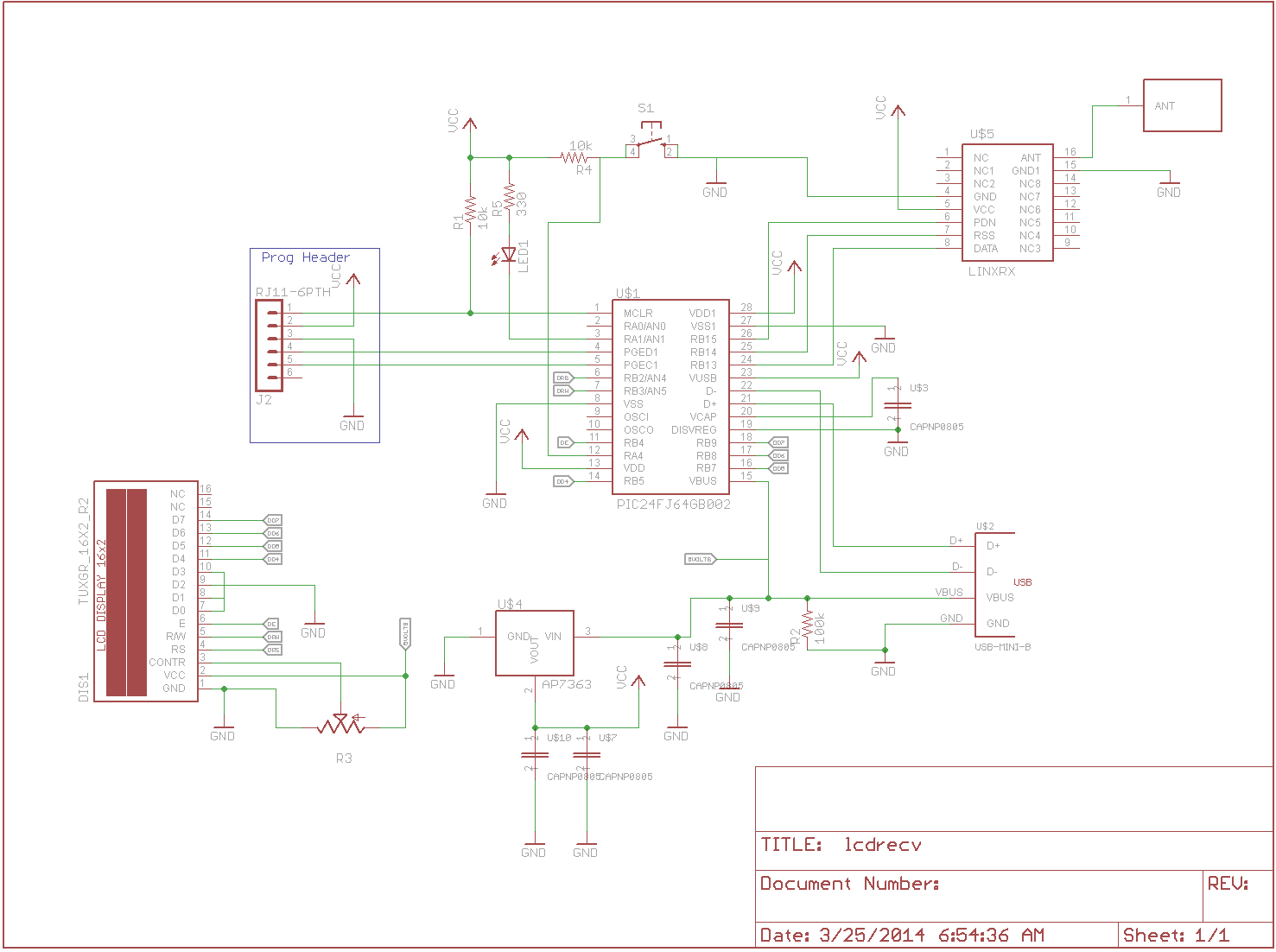
Temperature Sensor Receiver with LCD Interface
The schematic is very close to what is in the USB receiver. The only addition is an LED, a button, and the LCD. I used the programming header to get the boot loader into the processor but after that I used the USB boot loader exclusively to upload software to the processor. This is very similar to the development cycle employed by the Arduino.
Once I had the hardware modified to accept the LCD. I set about to get the firmware running. I used the original USB receiver to get started. With this code I used some code from the Raspberry Pi interface to upgrade the USB receiver code as I had changed the protocol from the temperature sensors a bit. Once this code was working I then proceeded to add the LCD to the mix. I made sure that the library I was using had the LCD routines in it and changed the pin assignment in the LCD initialization routine to match how I hooked it up. Once that was done I tried to put some characters on the LCD but nothing showed up. My first pass I didn’t ground the unused data pins. Once I did that the display started working.
With the display working it was time to actually put some temperatures on the display. I have 2 lines by 24 characters on my displays. This is a bit bigger than the typical displays which are 2×16 characters. I got a special deal on these displays. With the extra characters I was able to include a minimum and maximum temperature on the display as well as the current temperature.
I had an extra line to work with. As the display can cycle by pretty fast, I thought it would be a good idea to use the second or extra line of the display to always show a particular sensor the user is interested in. This special interest sensor could be chosen by the button. By pushing the button the user can cycle through the sensors that the display has heard and once the user stops pushing the button the sensor that is being displayed on the extra line would stay there and be updated each time the display received some information from that sensor. This way the user can keep track of say an outside temperature of interest. I currently have 10 sensors spread around my house. I have several in different rooms of my house and 4 sensors outside my house. It is interesting to see the differences between the various sensors.
With the temperature sensor display it is easy to monitor the sensors and focus on one sensor of interest. The display is USB bus powered so any cell phone charger that has the appropriate USB connector can power the display. You can even use a battery used to charge cell phones to power the device. This gives you a portable temperature display device.
This project was a lot of fun. Once the LCD interface routines were included in the library the project was very easy to put together. Once the hardware was modified to accept the LCD interface, which took about a 1/2 hour I was able to get the firmware all working in about 2 hours. That is record time for a project such as this. My next step is to put it in a case so that I can protect the electronics and give my wife a nice package she can keep on her desk as she is always interested in the outside temperature.
My next step is to incorporate some moisture and humidity sensors in the mix. I have examples of both moisture and humidity sensors I have acquired and am anxious to add them to the temperature sensors.