The Engineer Tutor
Learn from our Experience


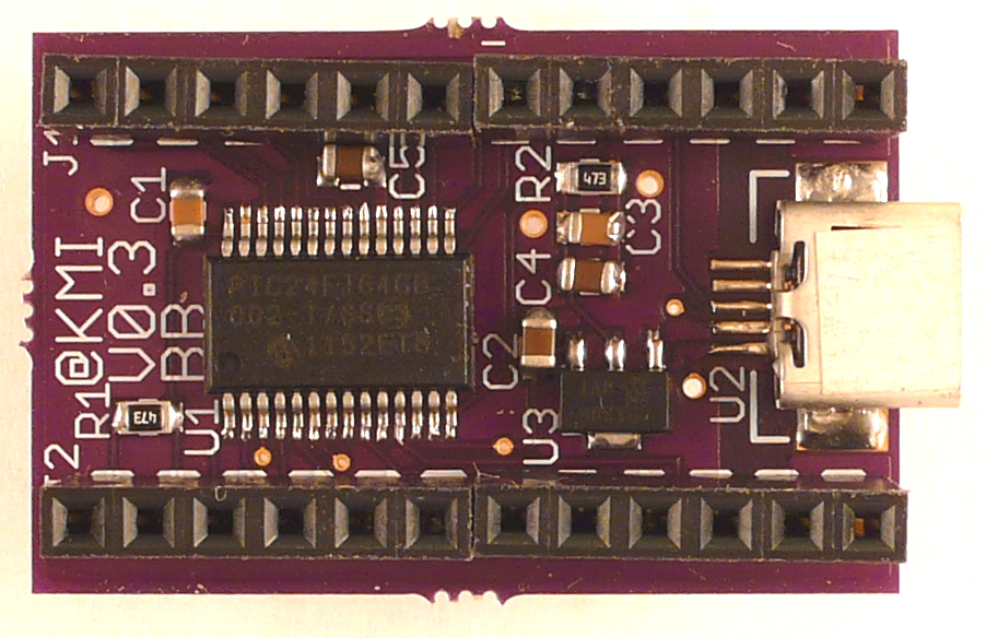
We have been working on laying out a board. It is a very small PIC24FJ64GB002 board. The board has a USB connector for power, programming, and communication. The board has a USB boot loader programmed into the chip which will allow you to change firmware without the need for some sort of programming device such as a PICKit 3 or something similar.
We are on our third version of the board. We had some issues with the PIC24FJ64GB002 foot print and made a change to the board to give other boards you might plug into it access to the 5 volts directly from the USB connector. We thought this would be a good idea as the 3.3 volt voltage regulator will only handle like 250ma. With access to the 5 volts from the USB, daughter boards can have their own regulators if necessary.
We plan on including connectors similar to those on an Arduino such that other boards can be plugged into these boards to form complete working systems. With these connectors boards will stack in the same way as the Arduino. We are waiting for the third version to be built and sent. We understand the boards are at the board house being made currently.
We are using OSH Park as our board house. They aren’t the fastest way to get boards but their prices are very good. The quality of the boards is acceptable. We have been able to make version 1 and version 2 of this board work without any wires.
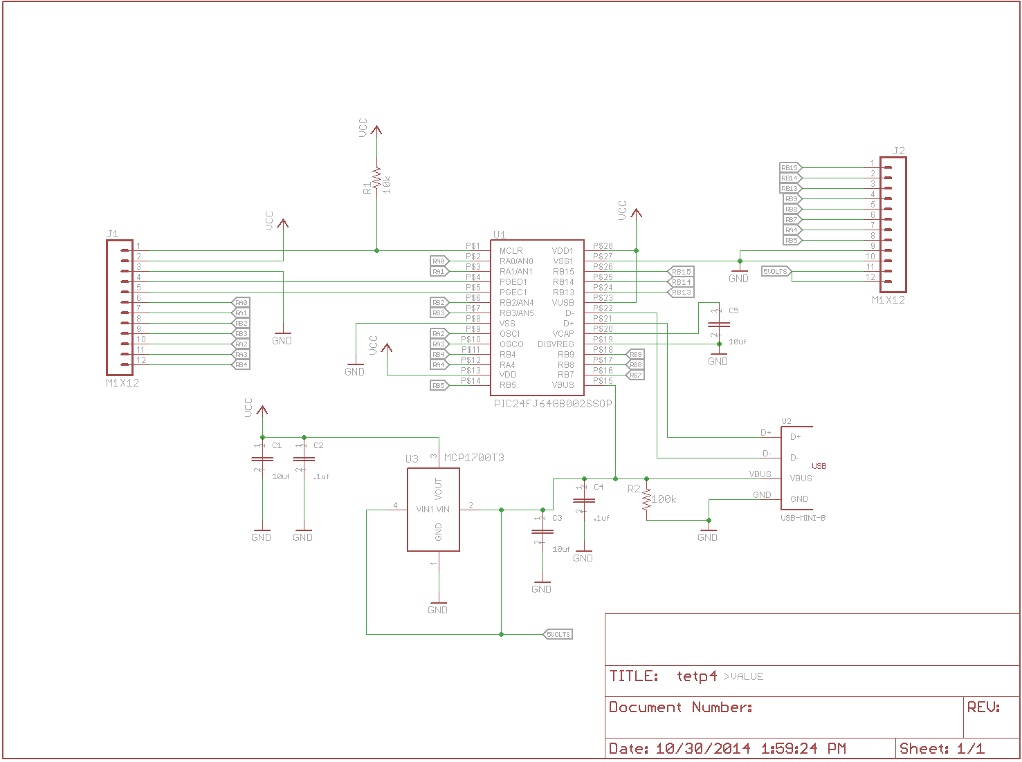
From the schematic you can see that there are 17 lines of I/O. Some of these lines supports the PPS of allowing functions to be assigned to pins. Through the next few weeks we are going to redo some projects we have presented here already and show you both with code and with hardware how to interface with this board.
We also plan to add many different boards that can be stacked on this one. One of these boards is a board that contains a serial EEPROM (I2C) and a temperature sensor. This will be a mini temperature sensor board. We also have plans for another board that contains an RF transmitter/receiver. This combination will support a battery to give you a remote sensor.
Another board we are looking at doing is one that would allow you to plug in a PICKit 3 to program the board if you so choose. If you look at pins 1-5 of the external pins on the board you will see a PICKit 3 compatible programming port. This port is complete with the data lines and the power and ground necessary to program the part. This is how we get the USB boot loader into the part.
The pins have the following assignment the connector on the left:
The second connector on the right has the following pin out
The I2C bus SDA1/SCL1 and SDA2/SCL2 are not able to be remapped. They are assigned to these pins in the hardware and can’t be changed. That is why I marked them as such in the pin enumeration.
The program used to program the board is the Microchip HIDBootLoader (Windows).exe located in the USB\Device – Bootloaders\HID directory in the microchip solutions directory. This program will recognize the Blue Bird board and allow the user to load firmware into the device. This program takes a hexadecimal file that contains the binary information for the firmware to be loaded and programs the part in question. To put the part into boot loader mode you must ground pin 7 (RA4) of the second connector or the right connector to get the device to go into programming mode. This pin (pin 7/RA4) should be pulled high to execute your application. Once your application is running you can use this pin for other functions as long as you can pull this line low to put the device into the boot loader mode. Once you load the Microchip boot loader windows software it is fairly obvious what to do. You can load the file you want to program, program the part, and you can also reset the part to execute the application. Make sure RA4 is pulled high to run your application.
The RA4 pin gives you a fail safe way of getting into the boot loader just in case your firmware isn’t able to do it. We will show you ways in which you can smoothly get back to the boot loader without using RA4 to do it. This will be in another tutorial about the board.
Building the boards by hand took a microscope to get the processor put down correctly. Especially with the problems we had with the foot print on the processor. But, with some excellent soldering skills we were able to get the processor soldered down and it actually worked. We have since corrected the foot print and eagerly await version 3 of the board to verify that the processor foot print is going to work for us. The rest of the board only required a 5x magnifier which makes building the boards a little easier than using the microscope. The 5x magnifier has a larger viewing area than the microscope. Even with the difficulty of the processor our tech was able to knock out a board in about 6 minutes. He is really good. We are looking for a CM right now.
Hope you like this board. Look for it soon on this site for you to purchase.