The Engineer Tutor
Learn from our Experience


I have always wanted to get the Microchip example code of the USB HID boot loader working for the PIC24F64GB002. I decided that the time has come and I sat down and started working on it. That was Saturday before last. I wasn’t successful but, tried it again during the week and I got it to work at least it would enumerate as an HID. The next step is to get it load some firmware and execute it. The next Saturday I had some time and cooked up an application that I hope would work with the boot loader. I used the linker script that came with the HID boot loader code for the application. I down loaded the application (LED blink) and gave it a try. It didn’t work. I started reading documentation about the boot loader and from what I could tell it should work. I looked at the circuit again and found that the LED was in backwards. I switched the LED around and the program was actually working.
I was surprised at how quickly I was able to get the boot loader working and get an application loaded to it. I’m going to show you the hardware I used to get the HID boot loader working and how to build applications for it. This really makes it easy to program the PIC. You don’t have to have a PICkit 3 or any other type programmer. The chip can self program. The only problem is you need a part with the boot loader programmed into it.
Like I said the first application I have loaded on the board blinks an LED. What else would you start with. There are a couple of switches that I’m using. One grounds the MCLR pin to cause a reset in the part. The other switch is attached to RA4 which is used by the boot loader to tell if you want to go into boot loader mode or try and execute the application. If you push this button then push reset and release reset the part will go into boot loader mode and you should hear the board enumerate on the PC. Now you just have to bring up the Microchip boot loader app to load a new application into the board. It is that easy.
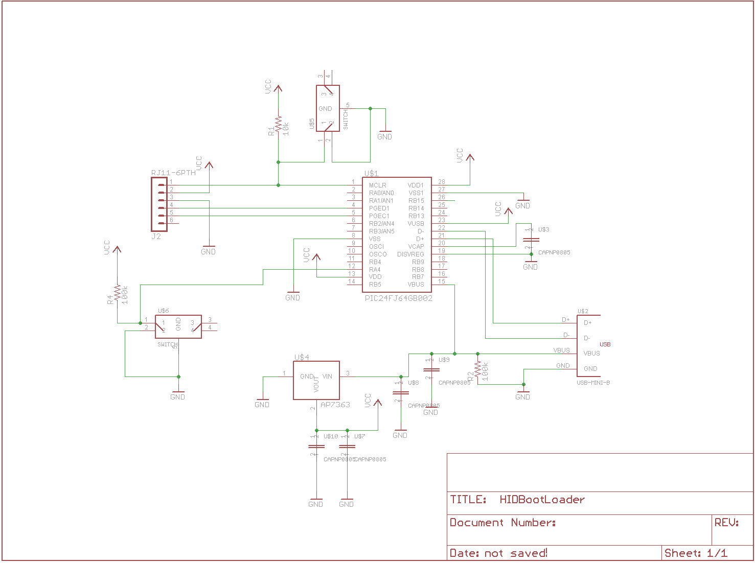
HID Boot Loader Schematic
In the above schematic you can see the two switches that were added. One to the reset line and the other one to RA4. The boot loader looks at RA4 to see if it is low. If it is low it stays in the boot loader to allow you to recover the board.