The Engineer Tutor
Learn from our Experience


Wireless Sensor Boards
I have been working on my wireless sensor project and have been making my own boards. I’m getting better at it. I switched to muriatic acid for an etchant and that has cut down on the etching times. I also decided to make the board entirely surface mount. This clean things up a bit and also makes the board a bit smaller. Another thing I like is the lack of components on one side. This makes the board smooth on that side and allows me to use double sided tape to stick them places. I also wanted to eliminate the programming header. I wanted to use something I could just press on the board and program it once.
Pogo Pins
I remember a tutorial I watched on Sparkfun once about Pogo pins. These are cool pins that are spring loaded. The showed how to use them in testing new products. They showed a test jig they built that they slipped the board into and they all used Pogo pins to make the electrical connections to the boards. I thought I could use the same trick to program my boards.
First SMD Board
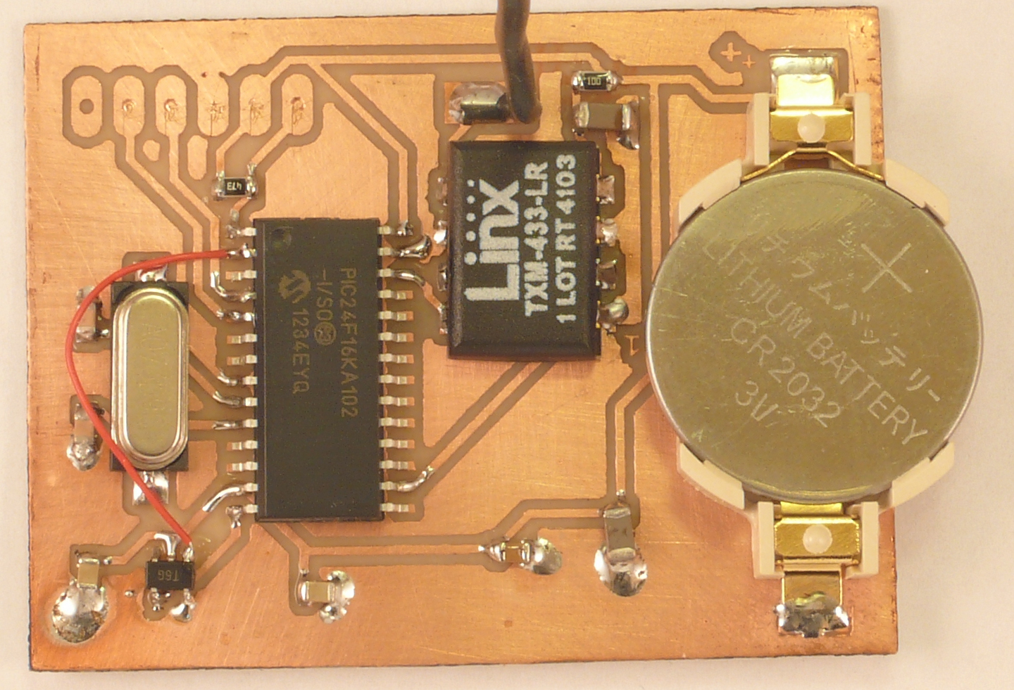
Top of Wireless SMD Board
My first SMD board came out of the etchant solution and I populated everything. I took my Pogo pin programmer and tried to program the board but, the picKIT 3 wouldn’t recognize my device. I checked all the connections and everything looked good. The board looked good the traces were straight and looked great. I couldn’t imagine what the problem was. I thought I would etch another board and build it slowly to see if I could figure out the problem. I did just that. I built another board. I put the processor on first and one resist for MCLR. I tried my Pogo pin programmer and it worked! I was able to program the processor. I added the crystal with its caps. It still worked. I added the transmitter with the same success. I added the battery and still was able to program the processor. I finished up with the bypass capacitors and the board was fully functional. With this knowledge I thought that the problem was with the way I built the board and not the board itself. I took my meter and checked the resistance between power and ground. Oh, they are shorted together. I looked at the board closely and decided the problem had to be with the bypass capacitors. I pulled them off one by one till I found the problem. I carefully put them back checking the resistance between power and ground after each capacitor and made sure there was no short. I attached the Pogo pin programmer and it programmed the part. That is a big problem with making your own boards. There is no solder mask and it is very easy to bridge traces or something else and cause a short. I knew this and in my trouble shooting I checked for shorts but, not between power and ground.
Pogo Pin Programmer

Pogo Pin Programmer
Here is a picture of my Pogo pin programmer. You can see the Pogo pin in a row. They are almost a dollar a piece so a little expensive. The first time I built the fixture I put the Pogo pins on first then tried to put the other components on the board. I bent the Pogo pins and they no longer worked. I tried to straighten them but it didn’t work. I purchased 20 pins so I had spares. I started again and this time I put the Pogo pins on last. That worked a lot better. Note put the Pogo pins on last. I used a bread board to keep the Pogo pins in line and at about the same height when I soldered them. You can see the way I solder them so when pressure is applied to the pin it pushes against the single sided pad of the proto board and doesn’t push them out as there isn’t a lot of strength in single sided proto boards. I only used 5 pins as that is all that is needed with the PICkit 3. The pins are expensive.

Pogo Programmer Side View
This picture gives you a good view of the pogo pins. You can see how long they are to accommodate the spring the have in them. Here you can see the programming connector for the picKIT 3.
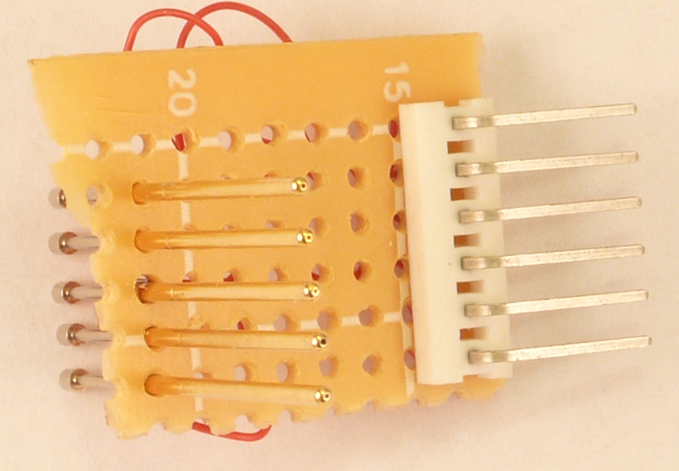
Pogo Programmer Bottom View
The bottom view shows you the pogo pins again. I’m still surprised at how long they are.
It works
I’m happy with the way the programmer turned out. You have to be careful with it as the pins are a little susceptible to bending which causes binding and they don’t work very well.