The Engineer Tutor
Learn from our Experience


I was working in my shop the other day and realized that I needed a light for a webcam that I setup to show a circuit to a colleague of mine. I set it up and then left it on as he works different hours than I do. I had to leave the light on for a few days as he worked on it. I took my dogs outside for their amusement and noticed the light on in my shop. I knew what it was for but, thought it would be great if I could turn it off and give him remote access to my computer to allow him to turn it on when he needed it.
I had an old power strip laying around that had an on/off switch on it. I wondered how the switch was wired. If I attached a couple of wires to the switch in parallel I could wire a relay to also apply power as the switch does. I tore apart the power strip and looked at the switch. The switch was perfect for doing this. The only problem with this is when the switch on the power strip is turned on the relay couldn’t turn it off. I thought this was an acceptable limitation. It allows you to turn on the power strip via the switch without having to activate the relay. My power strip was made by Fellows. There is no surge supression in it but, I plug it into a surge supression power strip.

Fellows Power Strip
I set about creating this small board to allow a computer to control a light plugged into a power strip. I added the necessary wires to the power strip and put it back together. The connection looks like the following:

Internals of Power Strip
You can see the two wires I added to the switch. The bottom lug in the above photo is attached to the mains live wire (black) which is the line that is switched in and out. The two wires run to a relay that bridges the switch when the relay is active thus turning on the power. I believe most any power strip with an on/off switch would have a similar configuration. With the power strip modified you can put it back together.
Now to go to the logic board. You must be careful as to how you wire the power to the relay. You have 5 volt logic possibly 3.3 volt logic to worry about. If a power wire should come loose and come into contact with the logic supply it would certainly mean the death of your sensitive logic components.
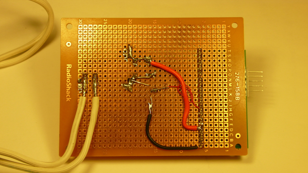
Back of Board
This is the way that I have wired the relay. You can see that I have used a generous amount of solder to hold down the power wires I’m switching and have attached those to the relay. I also added a tie down to hold the wires in place should anything happen to them. Refer to the schematic for information on how to wire the relay to the microcontroller. Make sure that you wire the power wires to a normally open set of contacts on the relay. This will allow you to turn on power by energizing the electromagnet in the relay. If power is removed from the logic board it will turn the power strip off. This is usually a desirable function.
I obtained the proto board from Radio Shack. You can see the part number in the photo above. The top of the board shows a neat installation of the components.
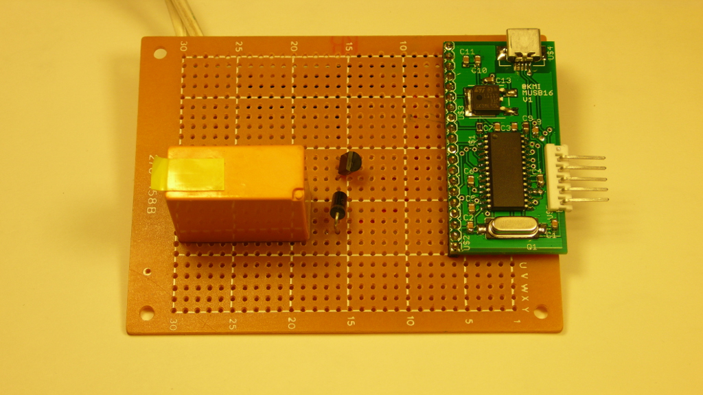
Front of Board
The logic board on the right is one of my own design. It contains a 24FJ64GB002 processor by Microchip. I chose this processor because of its USB interface. This USB interface provides a virtual com port on a windows PC. You can access this virtual com port using a terminal program such as TeraTerm or other program to activate the power strip.
The software can be found online. It is based on the USB example that Microchip provides on their web site for their processors that support USB. I have modified the software slightly to allow me to turn the power strip on by typing a “p” (lower case p) and turning it off by typing a “o” (lower case o). I have used this circuit many times in test fixtures and to apply power and turn the power off. It has been very robust.
I have been thinking that I could add a sensor to the board to detect my presence and turn on the light when I enter the room. I could also add a light sensor to only turn on the light when the room is dark. Both of these additions would be fairly easy to do.
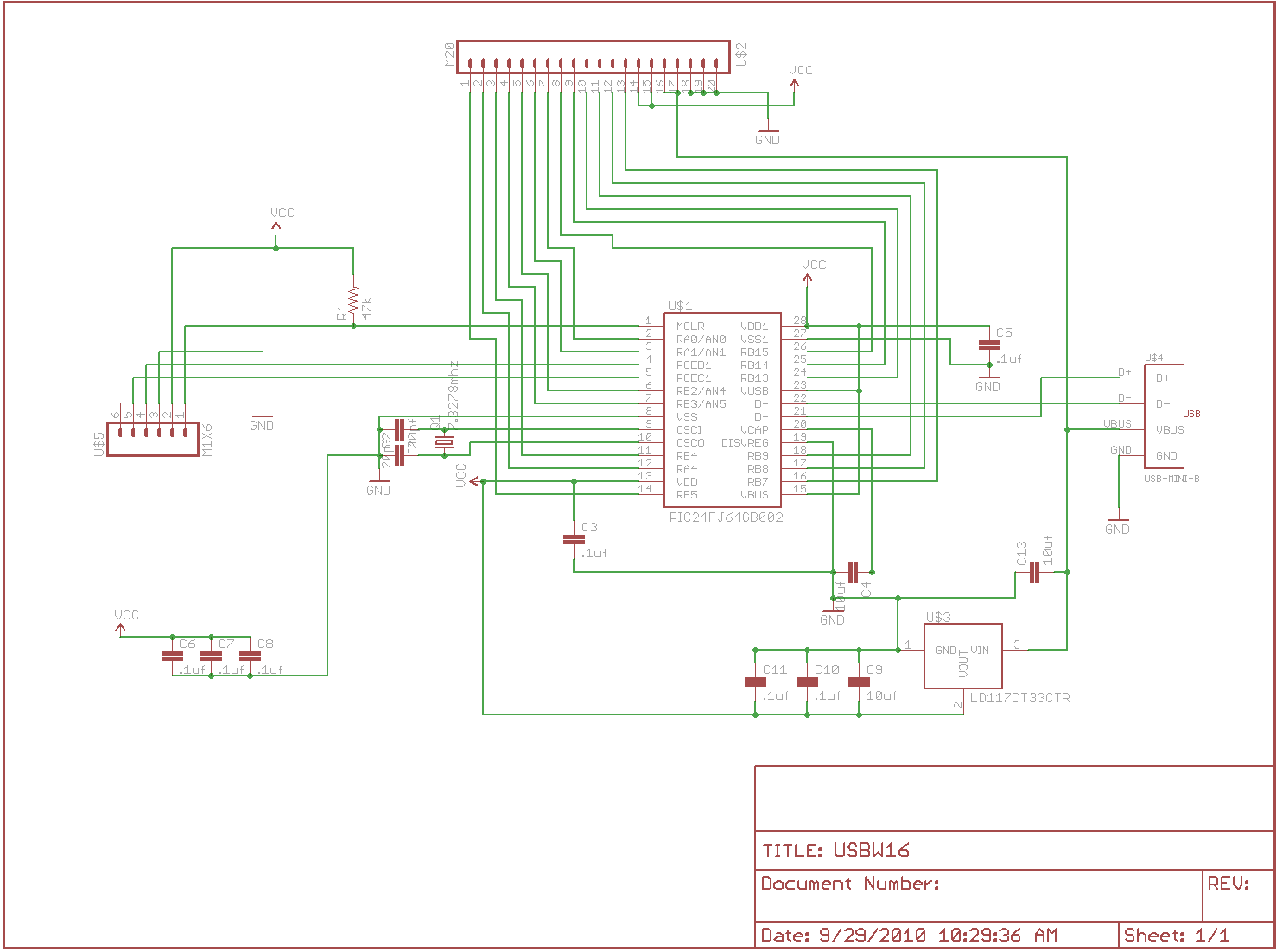
Schematic of Board
This is the schematic of the small logic board. You can see that it is fairly simple and contains just enough circuitry to support the processor and make it work. It interfaces with the outside world through the 20 pin connector (U$2) on the side of the board. The connector U$5 is the debug connector which I use to connect a PICKit 3 to program the board.
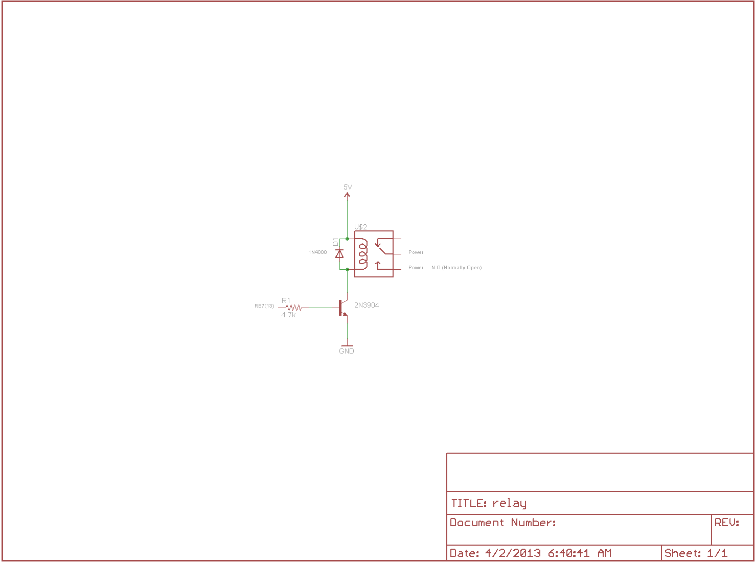
Relay Schematic