The Engineer Tutor
Learn from our Experience


Well, for this installment I plan to go back to the blinking LED. I know we have already done that. But, you will see that this is very different than the last version of the blinking LED. Wire up a new LED according the schematic. We are going to vary the intensity of the LED using a PWM signal. This is a very useful tool. It can also produce analog signals with the proper filtering.
Here are the connection required for the PWM LED.
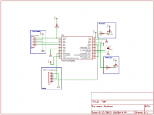
Pulse Width Modulation Schematic
We need to do a little setup. We need to tell the microcontroller which pin we want to do the pwm on. As you can see from the code we use the pwmOutPins routine. The first argument is the pwm number (0-4) and the second number is the pin that we can output the pwm on. This is the standard pins 11, 16, 24, 25, and 26. This case I’m using pin 25 in the code.
#include <p24fxxxx.h>
#include "rtos.h"
#include "pins.h"
#include "initializeSystem.h"
#include "uart1.h"
#include "uart1Pins.h"
#include "pwmPins.h"
#include "pwm.h"

#define FIVE_MINUTE_DELAY 5
#define TEN_MINUTE_DELAY 10
#define TWENTY_MINUTE_DELAY 20

unsigned int on = 0;

//
/******************************************************************************
 * Function void blink(void)
 *
 * This function is called by the RTOS when the delay has expired.  Interesting
 * to note that you have to call the delay routine again to get another delay.
 * The LED is flashed in this routine.
 *
 * PreCondition:    None
 *
 * Input:           None
 *
 * Output:          None
 *
 * Side Effects:    blinks the LED and also toggles the on variable between 1 and
 *                  0.
 *
 *****************************************************************************/
void
blink(void)
{
  if (on)
  {
    digitalWrite(16,HIGH);
    on = 0;
  }
  else
  {
    digitalWrite(16,LOW);
    on = 1;
  }
  if (!delayMS(blink,500))
  {
    runNext(); // next item to be run
    // wasn't able to add to the delay queue.  It must be full.
    // Try again.
    while (!delayMS(blink,500))
      runNext();
    // or you could setup an infinite loop to catch the error in
    // a debugger.
    // while (1)
    //    ;
  }
}

void
serial1Handler(void)
{
  int sChar;

  while (uart1IsChar())
  {
    sChar = uart1GetChar();
    uart1put((unsigned char)sChar);
  }

  // wait for next character
  while (!queueSerial1(serial1Handler))
    runNext();
}

unsigned int val = 10;
unsigned int dir = 0;
#define BLINKSPEED 10

void
pwmTest(void)
{
  if (dir)
  {
    val += 1000;
    if (val > 63000)
    {
      dir = 0;
    }
  }
  else
  {
    val -= 1000;
    if (val < 2000)
    {
      dir = 1;
    }
  }
  analogWrite(0,val);
  //analogWrite(1,val);
  //analogWrite(2,val);
  //analogWrite(3,val);
  //analogWrite(4,val);
  if (!delayMS(pwmTest,BLINKSPEED))
  {
    runNext(); // next item to be run
    // wasn't able to add to the delay queue.  It must be full.
    // Try again.
    while (!delayMS(pwmTest,BLINKSPEED))
      runNext();
    // or you could setup an infinite loop to catch the error in
    // a debugger.
    // while (1)
    //    ;
  }
}


/******************************************************************************
 * Function:        void main(void)
 *
 * PreCondition:    None
 *
 * Input:           None
 *
 * Output:          None
 *
 * Side Effects:    None
 *
 * Overview:        Main program entry point.
 *
 * Note:            None
 *****************************************************************************/
int main(void)
{
  initializeSystem();

  pinMode(16, OUTPUT);

  // make serial pins inputs
  pinMode(11, INPUT);
  pinMode(24, INPUT);

  // map rx pin to pin 11 and tx pin to pin 24
  uart1Pins(11,24);
  uart1Init(9600);

  // map pwm0 to pin 25
  pwmOutPins(0,25);
  pwmInit();

  while (!queueSerial1(serial1Handler))
    runNext();

  while (!delayMS(blink,500))
    runNext();

  while (!delayMS(pwmTest,BLINKSPEED))
    runNext();

  while(1)
  {
    runNext();
  }//end while
}//end main