The Engineer Tutor
Learn from our Experience


The next step is doing a serial interface. This seems to be a logical step in our exploration of this library. There is a module to give you a serial port and the PIC hardware supports a serial port which doesn’t take much time at all to handle. You can run it at various baud rates but it does take some configuration to get it to work.
A serial port takes parallel data written by the microcontroller and turns it into serial data. It then takes serial data and turns it back into parallel data for the microcontroller to read. That is the basic function of a serial port.
To configure the serial port we need to first set a couple of pins of the microcontroller to be the serial transmit and the serial receive. To do this we call the following routine. There are only a few pins that can be used as the serial transmit and serial receive. The following pins can be used.
Pin 11, 16, 24, 25, and 26
To setup pins 11 and 24 as receive and transmit respectively you would do the following:
uart1Pins(11, 24);
Here is a full schematic of the additional serial port connection.
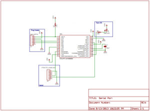
Serial Port Connection
That would do it. The following code implements what we have been talking about. To test this code you will need a TTL RS232 to USB adapter cable. These can be found at Sparkfun. The cable is simple to hook up. If you have configured the pins as suggested in the above tutorial simply hook the black wire to ground, the yellow wire to pin 24, and the orange wire to pin 11. That should get you hooked up. Now use Teraterm or some other terminal program setup at 9600 baud. Type some characters and they should be echoed back to you if all is working.
#include <p24fxxxx.h>
#include "rtos.h"
#include "pins.h"
#include "initializeSystem.h"
#include "uart1.h"
#include "uart1Pins.h"

#define FIVE_MINUTE_DELAY 5
#define TEN_MINUTE_DELAY 10
#define TWENTY_MINUTE_DELAY 20

unsigned int on = 0;

//
/******************************************************************************
 * Function void blink(void)
 *
 * This function is called by the RTOS when the delay has expired.  Interesting
 * to note that you have to call the delay routine again to get another delay.
 * The LED is flashed in this routine.
 *
 * PreCondition:    None
 *
 * Input:           None
 *
 * Output:          None
 *
 * Side Effects:    blinks the LED and also toggles the on variable between 1 and
 *                  0.
 *
 *****************************************************************************/
void
blink(void)
{
  if (on)
  {
    digitalWrite(16,HIGH);
    on = 0;
  }
  else
  {
    digitalWrite(16,LOW);
    on = 1;
  }
  if (!delayMS(blink,500))
  {
    runNext(); // next item to be run
    // wasn't able to add to the delay queue.  It must be full.
    // Try again.
    while (!delayMS(blink,500))
      runNext();
    // or you could setup an infinite loop to catch the error in
    // a debugger.
    // while (1)
    //    ;
  }
}

void
serial1Handler(void)
{
  int sChar;

  while (uart1IsChar())
  {
    sChar = uart1GetChar();
    uart1put((unsigned char)sChar);
  }

  // wait for next character
  while (!queueSerial1(serial1Handler))
    runNext();
}

/******************************************************************************
 * Function:        void main(void)
 *
 * PreCondition:    None
 *
 * Input:           None
 *
 * Output:          None
 *
 * Side Effects:    None
 *
 * Overview:        Main program entry point.
 *
 * Note:            None
 *****************************************************************************/
int main(void)
{
  initializeSystem();

  pinMode(16, OUTPUT);

  // make serial pins inputs
  pinMode(11, INPUT);
  pinMode(24, INPUT);

  // map rx pin to pin 11 and tx pin to pin 24
  uart1Pins(11,24);
  uart1Init(9600);

  while (!queueSerial1(serial1Handler))
    runNext();

  while (!delayMS(blink,500))
    runNext();

  while(1)
  {
    runNext();
  }//end while
}//end main
See the library configuration section of the getting started tutorial. It will show you how to get the library and how to take the above code and combine it with the library to create some working firmware.