The Engineer Tutor
Learn from our Experience


Build of materials for the blink LED tutorial:
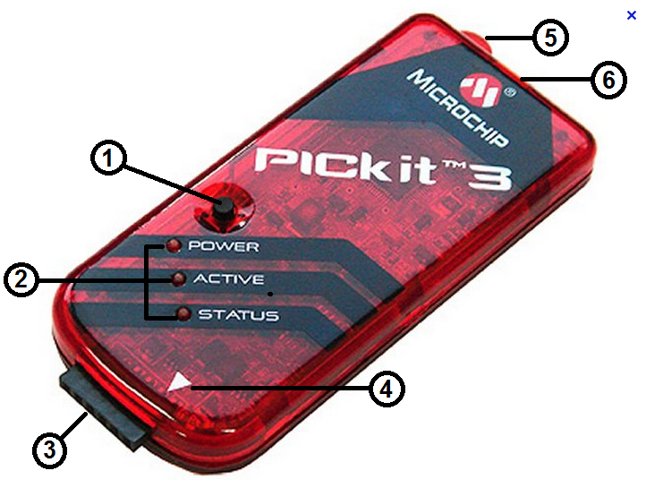
1.) Pickit3
2.) Breadboard
3.) 1pc. LED
4.) PIC24FJ64GA002
5.) 6 pins Connector
6.) Connecting wires
7.) 1pc. Capacitor 10uf
8.) 1pc. Resistor 330 ohms
9.) 1.pc Resistor 47k ohms
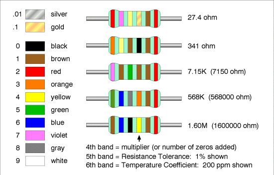
Resistor Color Coding (Click on image to enlarge): 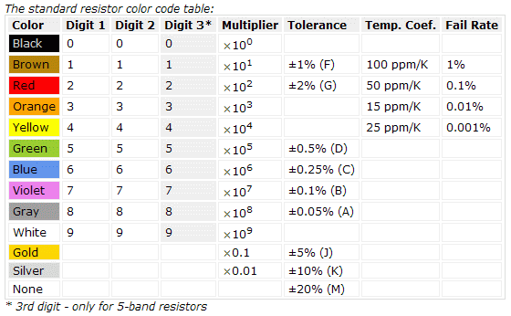
After installing those two software packages, MPLAB and the compiler we are ready to begin.
Next we need to run MPLAB and create a new project.
Step 1 – First, Double click the MPLAB IDE v8.88 Icon on your desktop.

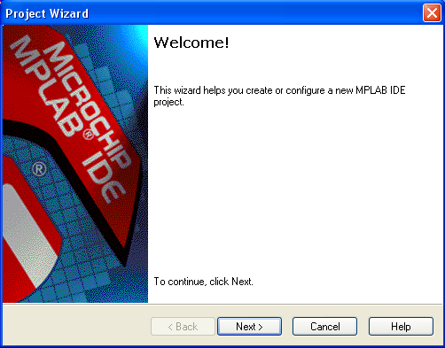
Step 2 – Run the Project Wizard under Project.

Step 3 – Click next to continue.
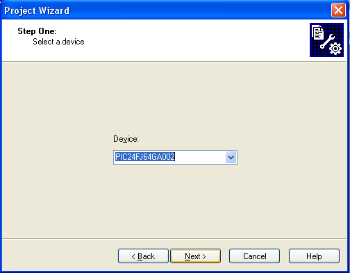
Step 4 – Make sure you set the part to PIC24FJ64GA002.
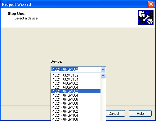
Step 5 – After selecting the device click next button
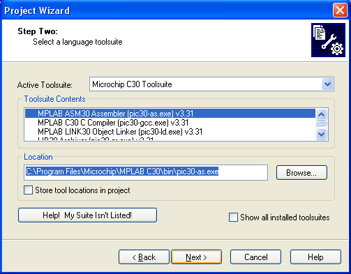
Step 6 – Choose the Microchip C30 Toolsuite in step two.
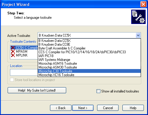
Step 7 – After selecting toolsuite, just click the next button.
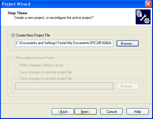
Step 8 – Then create a project directory.
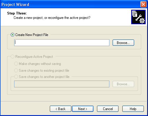
Step 9 – After selecting the file directory, just click the next button.
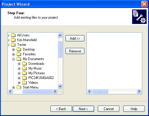
Step 10 – Step four is adding files but we don’t have one yet so just skip this and continue, click the next button.
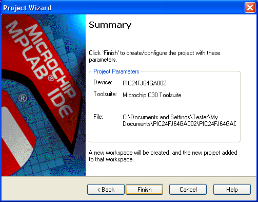
Step 11 – Just Click finish button to create the project with designated parameters.
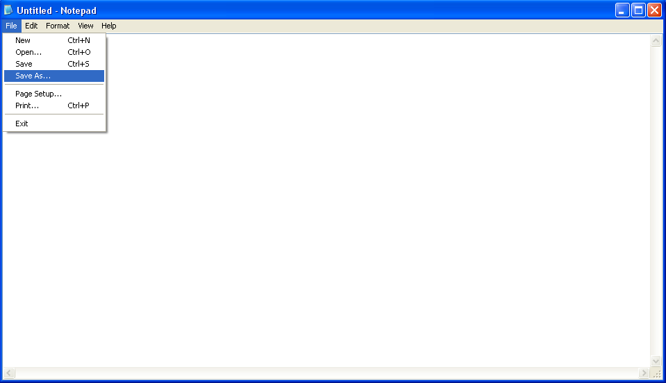
Step 12 – Now create a file with your favorite editor with an extension of .c. I used notepad as my editor.
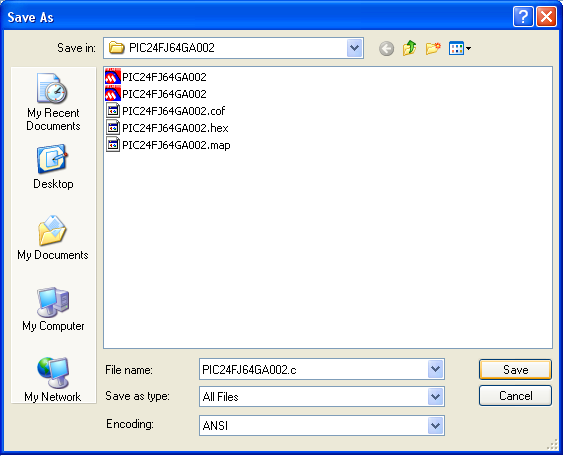
Step 13 – Save in the project folder you created, filename: examplefilename.c, Save as type: all files, then click save button.
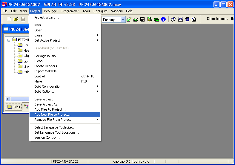
Step 14 – After saving the file go to “add new file to project” under the project menu bar and click it.
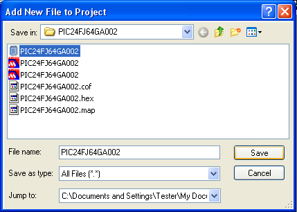
Step 15 – Select the file that you just saved to the project folder examplefilename.c and press the save button.
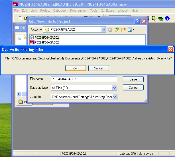
Step 16 – Just press the “Ok” button.
Step 17 – Now enter the following program on the file you have selected:
#include <p24FJ64GA002.h>
#define DELAY 2000
main()
{
TRISB = 0x0000;
T1CON = 0x8030;
while (1)
{
LATB = 0xFFFF;
TMR1 = 0;
while (TMR1 < DELAY)
{
}
LATB = 0x0000;
TMR1 = 0;
while (TMR1 < DELAY)
{
}
} // main loop
} // main

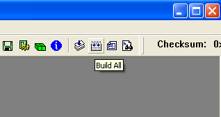
You should be able to build this.
Step 18 – Click the “build all” toolbar to build.
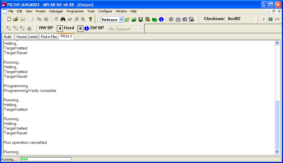
Step 19 – After clicking the build all toolbar, the result/output of the program is shown.

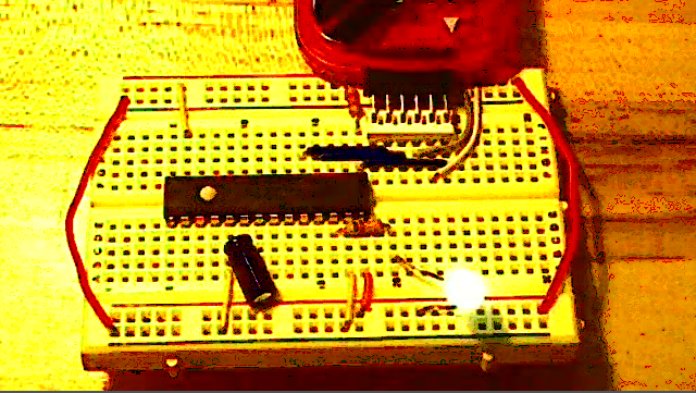
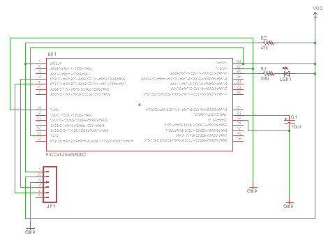
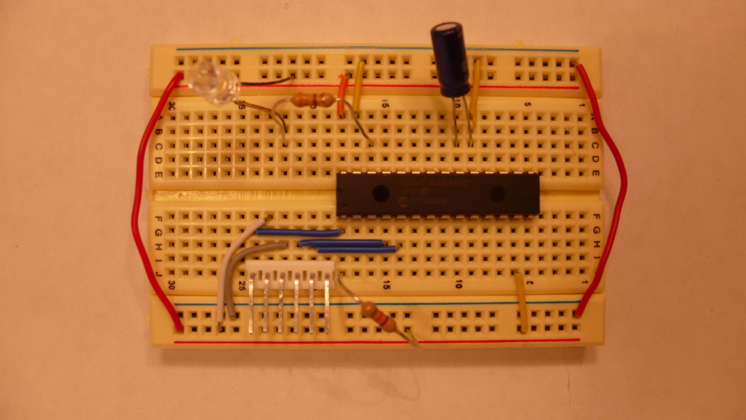
Step 20 – Now you need to wire the device according to the schematic and picture of my breadboard.
Step 21 – Hook up the Pickit 3 and program the device. To hook up the Pickit 3 we need to provide power to the processor on the breadboard. To do that go to the Debugger menu option and then select tool. Now select Pickit 3 from the list.

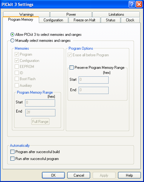
Step 22 – Now go to the Debugger menu option again and this time select settings at the bottom.

Step 23 – A dialog box should come up like this. Select the power tab.
Step 24 – Make sure the voltage is set to about 3.250 volts and click the check box next to the Power target circuit from PICkit 3 entry. This should connect you to the device and allow you to program it.
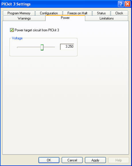
Click the apply button then Ok.
Step 25 – To program the device in debug mode do Alt+d g.

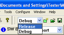
Step 26 – If you are in release mode do Alt+g g.
That should program the device for you.
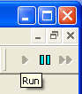
Step 27 – You can tell if you are in debug or release mode by the selection box in the middle of the menu in MPLAB.
Once it sees it you can program it. You should see the LED start to blink if you programmed it in release mode.
If you programmed it in debug mode you have to hit the green arrow to blink the LED. It should blink as long as you have power to the microcontroller.