The Engineer Tutor
Learn from our Experience


Wireless Temperature Sensor
I have always been fascinated by low power designs. I remember when I was attending the University of Utah and working on battery powered designs. Those designs would take 500-750 ma and sucked a battery dry in a few minutes. It was discouraging. I was using a Z80 and that wasn’t known for its low power consumption. I played with some CMOS designs which promised lower power consumption but, due to limited funds I wasn’t able to pursue this seriously.
Recently I have played with an MSP430 which is a true low power device. I have seen that device run on power it obtained through the I/O pins and nothing else. It was truly amazing.
Microchip XLP Parts
But, being a Microchip design partner I decided to see what Microchip had to offer in low power devices. I wasn’t disappointed. Microchip has several parts they have designated as “XLP” (extreme low power) devices. I found one that I liked, the PIC24F16KA102. This part comes in a 28pin DIP package. That makes it easy to bread board with.
I have wanted to build a wireless sensor network for a while now and thought that can be done with Microchip components. I took a PIC24F16KA102 and started developing a wireless temperature device. I grabbed a Linx transmitter and receiver to create the wireless link. I also took an LM36 for temperature readings.
I’m using a TXM-433-LR-S device from Linx Technologies. This device had the proper voltage range to work with the KA102. It also has a power down pin that makes it easy to put the transmitter into a low power state.
The TXM-433-LR-S is a “raw” transmitter. That means that it is up to the microcontroller to implement any protocol required to make the RF link work. A raw transmitter requires a constant DC offset. That means that any signal you send to the transmitter must be a logic zero as much as it is a logic high. The easiest way to accomplish this is with Manchester encoding. I’ll talk about this in a minute.
The Protocol
One thing I have found with this raw transmitters is the DC offset is very important and to get a transmitter started after being powered down you have to use a preamble to set the DC offset. I usually use a series of 5 or so 0x55 characters. If you look at this pattern using a logic analyzer or an oscilloscope you will see that the wave pattern of this character fills the bill for proper DC offset perfectly. Even counting the start and stop bit. Once the preamble has completed I like a start character to the actual packet. Traditionally I have used 0x7E which is a good pattern to use. The problem with that character is the DC offset isn’t very good in it. This is where the Manchester coding comes into play. It takes that character and splits it up into two characters that create a perfect DC offset to keep the transmitter happy.
The rest of the packet is composed of a count of the number bytes remaining in the packet, then the payload of the packet followed by a check sum and finally some characters similar to the 0x55 to round out the packet.
Transmit Only
The wireless temperature nodes only have the capacity to transmit. That means that they do it blind. The nodes have no idea if the message is getting through as they cannot receive. This makes for a simpler node and doesn’t require a receiver or two antennas or a complicated antenna switching scheme. You might say there are transceivers out there that help with those issues. That is true but I had these left over from another project and thought they would do the job.
Here is a picture of a start of the bread board. This includes the power and ground connection as well as the programming header. You can see a crystal attached to the processor. I wanted to run it without a crystal but the internal oscillator wasn’t accurate enough for a proper baud rate. The power consumption is still in the 5ua range in sleep mode on this. If my calculations are correct that gives a life of around 5 years with a coin cell.
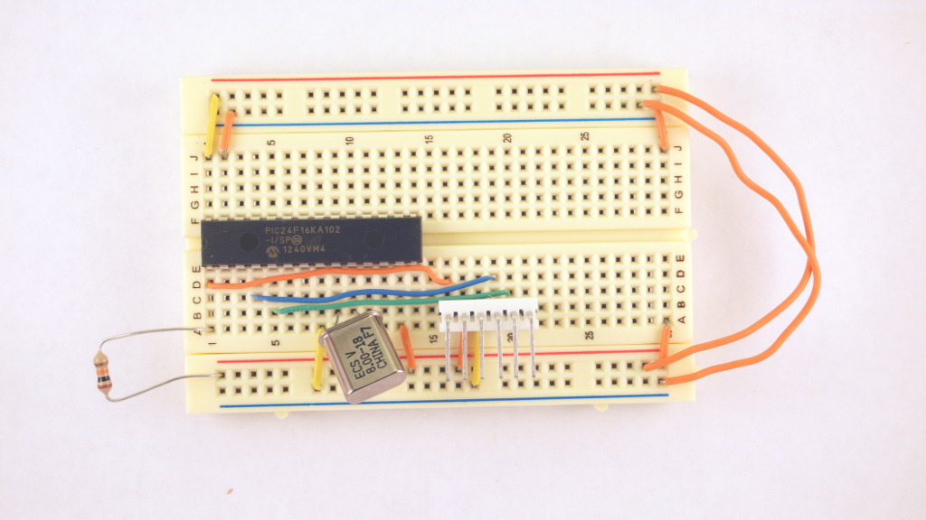
Wireless Temperature Sensor Power, Ground and Debug connections
Let me add the transmitter and battery holder to this.
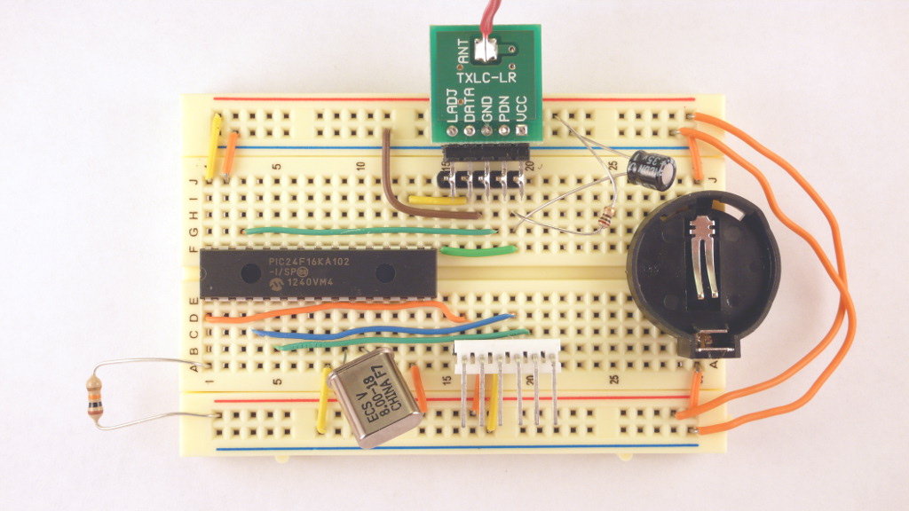
Temperature Sensor with Transmitter
Next I added the temperature sensor. This is an LM35 type. It is a surface mount part see here to see how to convert it to a through hole part.
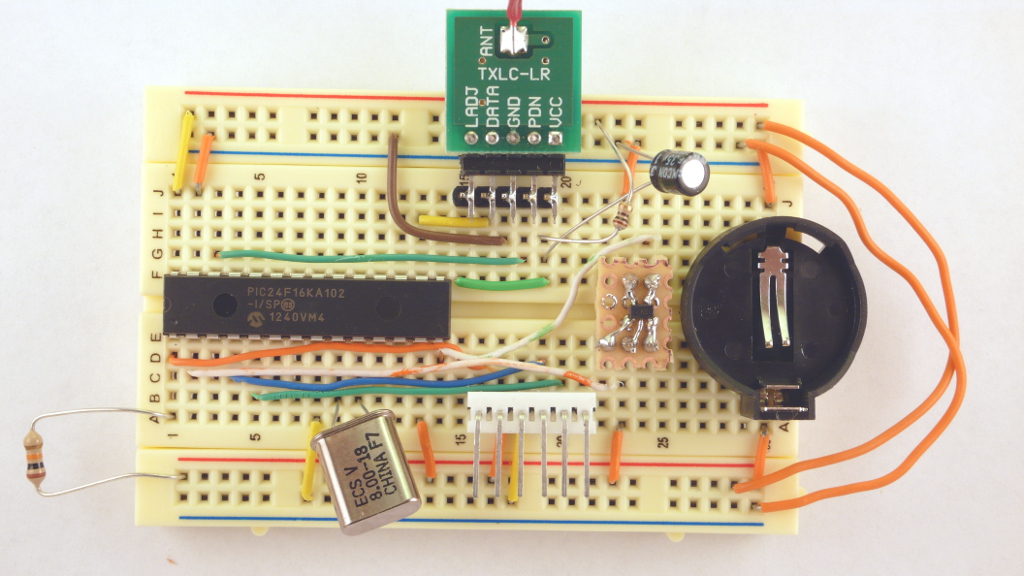
With Temperature Sensor
Now this is only half of the equation. You need some sort of interface to the computer to get these readings into a form that you can use them. Here is the schematic to the above bread board.
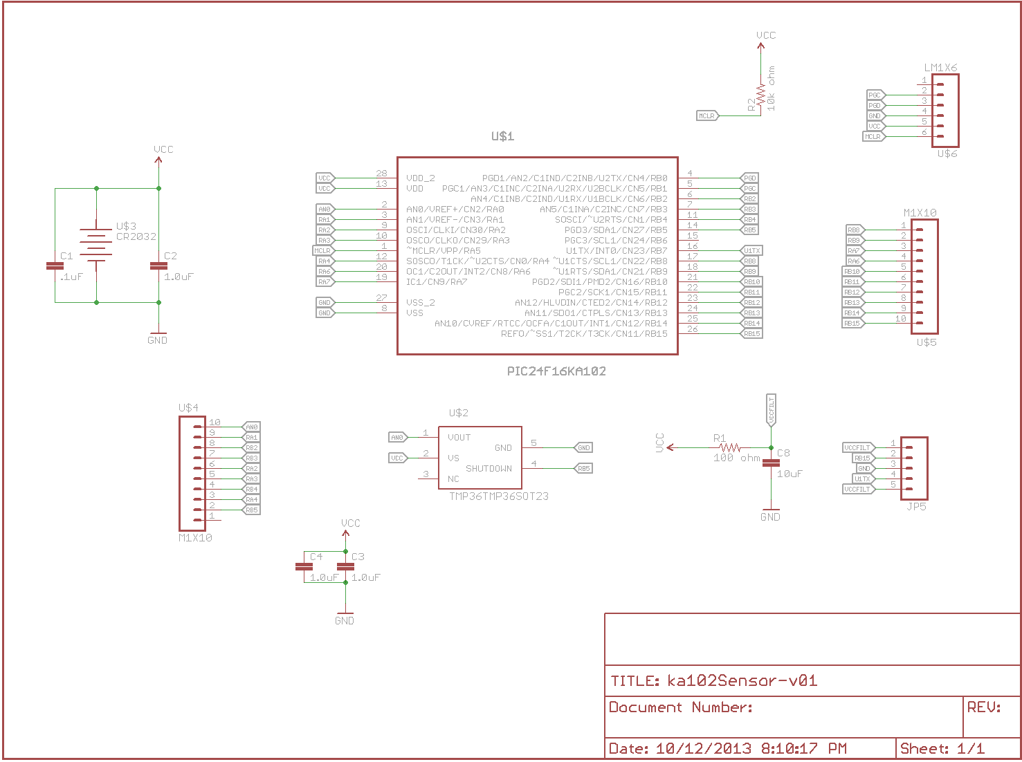
Schematic
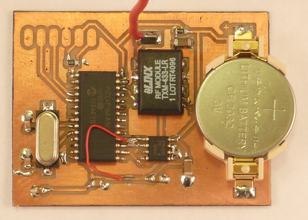
I etched my own board from the above schematic. I did it entirely using surface mount devices. This is what it looks like.
Top of Wireless SMD Board
You can see the PIC24F16KA102 and the Linx TXM-433-LR chips. The temperature sensor is the tiny part in the lower left corner. That is it for the IC’s. The wire coming up out of the board is the antenna for the transmitter. This board is a single sided board. I was able to run all the wires except one. The analog output from the temperature sensor to pin 2 of the microcontroller. That is why there is a red wire. No, it isn’t a mistake. With single sided boards you will almost always have jumpers for a few wires. I thought I was doing good to only have one jumper wire.
I have decided to make some changes to the sensor board. I would like to use an I2C temperature sensor. That should be more accurate than the LM35 I am currently using. I did that and came up with the following schematic for it.
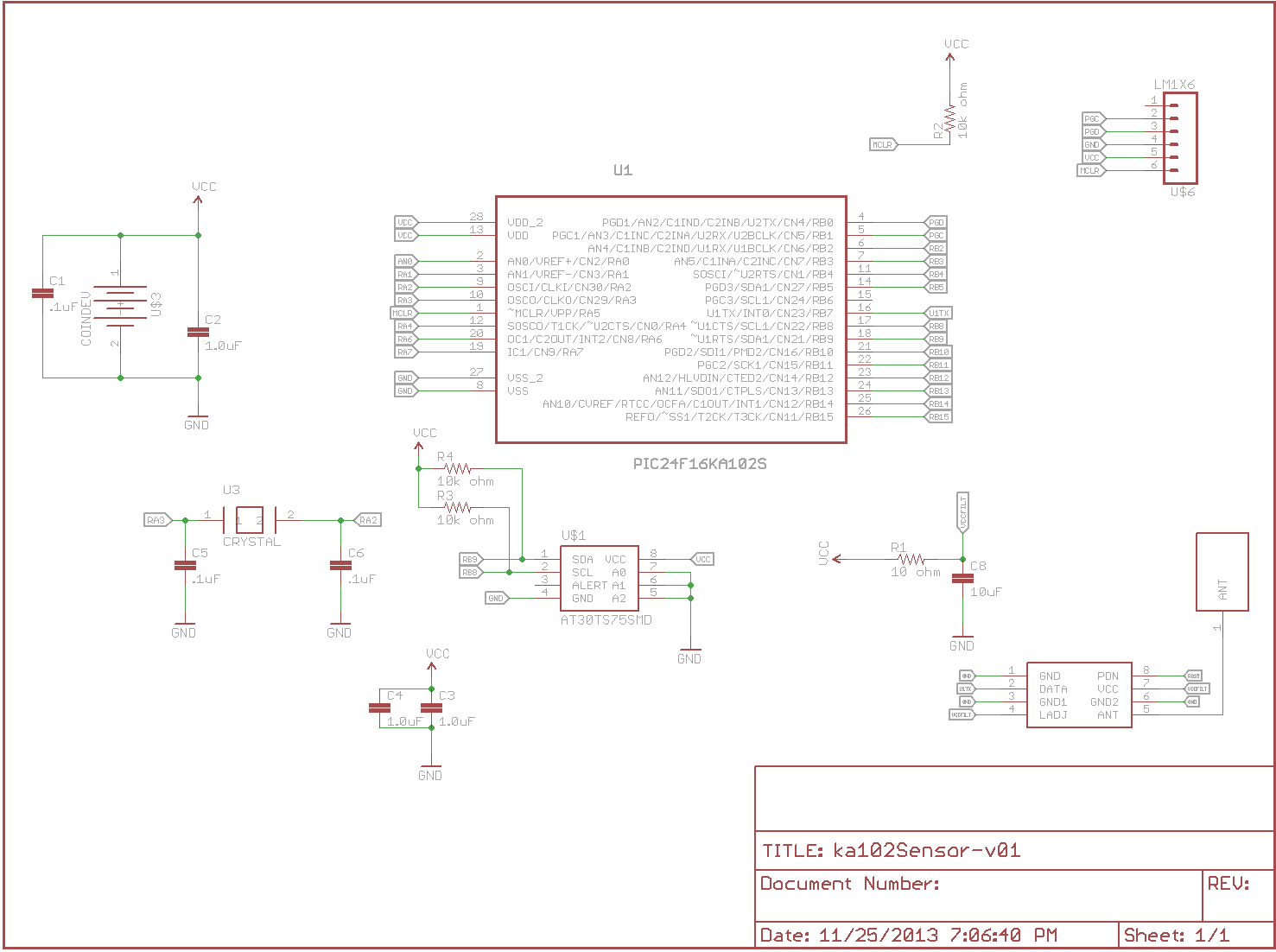
Schematic I2C Temperature Sensor
Again I etched my own boards and this is what I came up with.
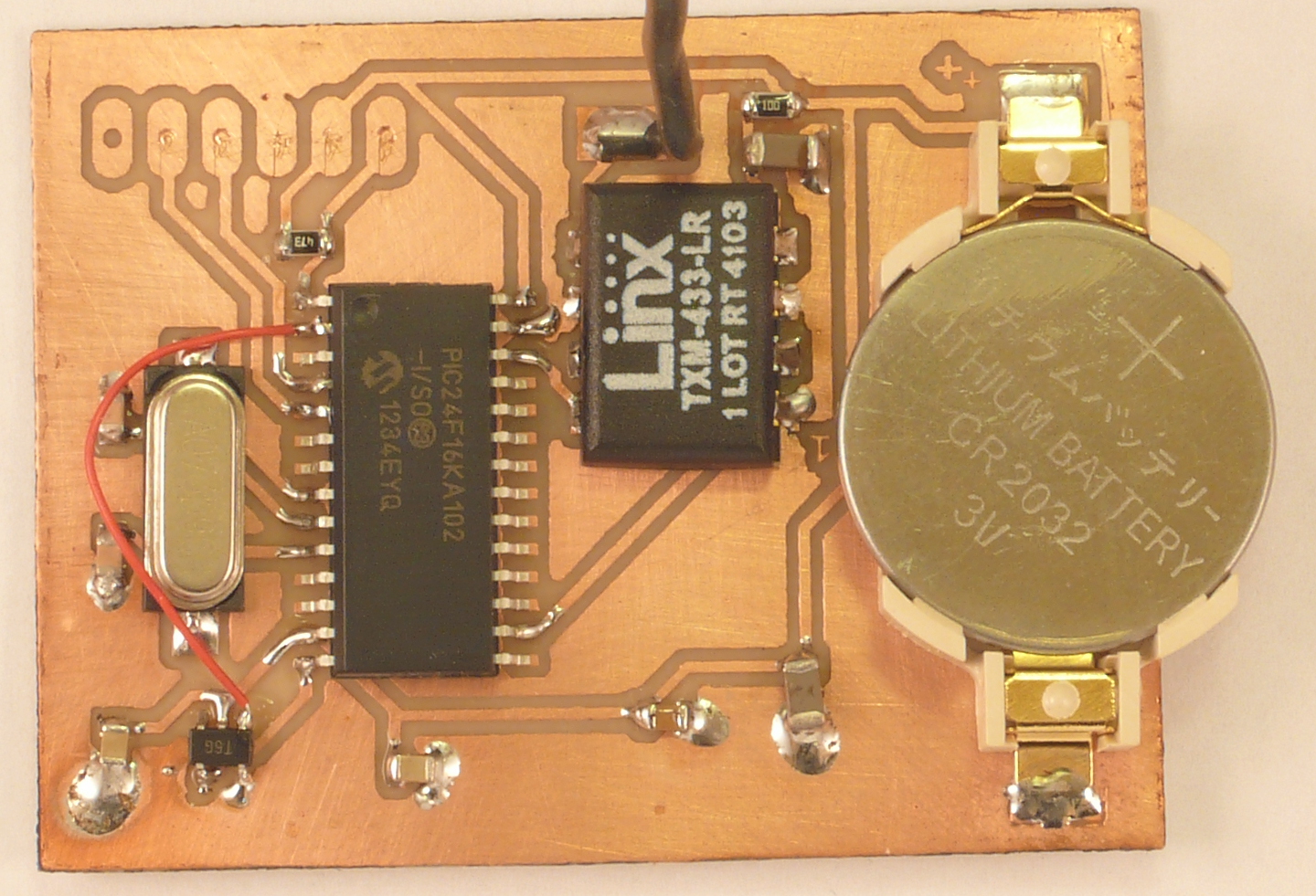
Wireless I2C Temperature Sensor
You can see the I2C temperature sensor below the transmitter inbetween the processor and the battery. I like the way this works much better than the analog sensor. It gives me direct temperature without having to figure out the voltage of the battery to calculate the temperature as in the analog sensor.
Wireless Temperature Sensor Receiver
I also finished up the receiver. Here is the schematic for the receiver.
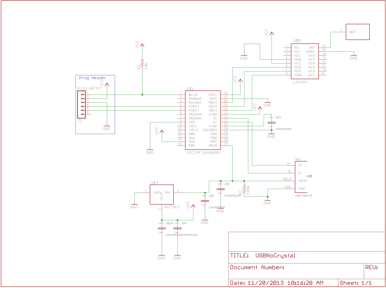
Wireless Receiver Schematic
Here is a shot of the receiver board.
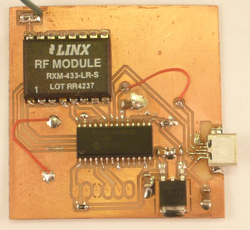
Wireless Receiver Board
You can see the receiver module in the upper left. Below the receiver is the PIC24FJ64GB002 processor and below that is a 3.3 volt regulator. USB gives 5 volts and needs to be regulated down to 3.3 volts as the PIC24FJ64GB002 can’t handle VCC much above 4 volts. I used the GB002 for its USB port that is plugged into a computer and with a serial terminal emulator such as teraterm you can see the packets coming from the temperature sensors. The red wires on the board are again not mistakes but jumpers required by the single sided board. One connects a couple of ground planes and the other one connects one of the USB data lines to the processor. I wasn’t able to get this wire hooked up with the single sided board.
When I first built this board I couldn’t get any power to the regulator from the USB connector. I made sure there were no shorts but upon further investigation I found that the power pin on the USB port wasn’t soldered down. Once I had that pin soldered down and having checked the other pins it actually worked. I was amazed that the first go at this board resulted in a working receiver.
I was talking with a friend of mine and we were talking about having a web site to collect the samples. I thought that would be a great idea but, I didn’t want to dedicate a PC to capturing samples from the sensors. I have a Raspberry Pi left over from a project I was working on with Element 14 that they gave to me and thought that would be perfect. So, late Saturday night I pulled out the Pi and after some digging I had a receiver hooked up to the Pi. A little bit of software and the Pi was receiving packets from the temperature sensors. Now to figure out how to get the data out to the web site. I’m using a Model B Pi. It has more memory and includes an Ethernet jack.