The Engineer Tutor
Learn from our Experience


Blinking LED is the “Hello World” of the embedded development. How exciting it is to get it to work! Now, what else could you do with the PIC? Where to go next? This posting is one of three that show you a couple step-by -step improvements to the blinking LED project. In this tutorial we will control three LEDs.
A note about voltage. I set my PIC to power the circuit with 3.25 V. That way I can simplify my circuit by not having to use voltage restricting resistors to protect my LEDs. Protecting your LEDs with resistors is a good idea, but I just wanted to simplify things for this exercise.
The first improvement that we will do is adding a couple of LEDs and controlling them separately
Look at the pinout of the PIC24FJ64GB002
")
PIC24FJ64GB002 Pinout (click to enlarge)
In the blinkie example, the LED is connected to the RB15 (pin 15 of PORT B, or pin 26 of the PIC).
Blinking LED
In the code, we set all pins of PORT B high:
LATB = 0xFFFF;
So it really doesn’t matter which pin of PORT B we connect the LED to. Try it. Add a LED to pin RB14 and RB13 (the next two pins right of the original, pins 25 and 24 of the PIC)

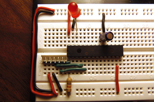
Three LED Blinkie
And the schematic:
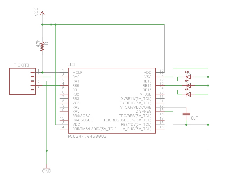
Three LED Blinkie (click to enlarge)
Launch your program again, and all three LEDs will blink at the same time. How to control them separately?
To set all pins high (light up the LED) we wrote to the PORTB through LATB, and set its value to 0xFFFF. Each F represents four bits:
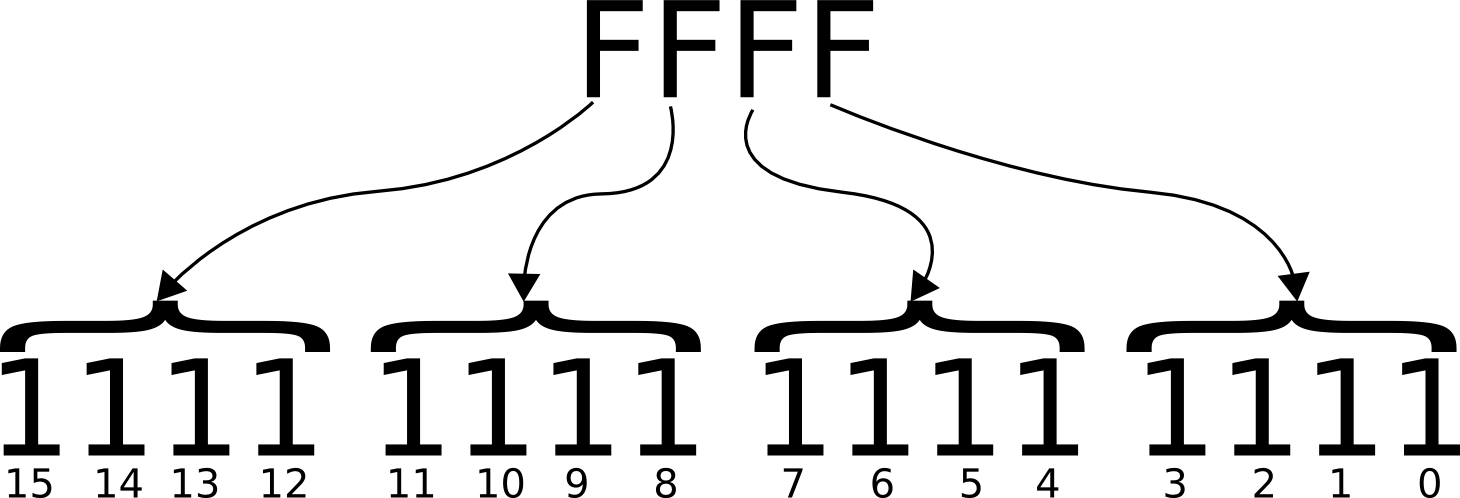
Binary Math (click to enlarge)
As the data sheet says, PORT B has 16 pins. Each bit in 0xFFFF represents one pin, 0-15 from right to left. So, to set pin RB15 on, you would write 1000 0000 0000 0000, or 0x8000 to LATB:
LATB = 0x8000;
To light up the LED in pin 24 (or RB14) you would write 0100 0000 0000 0000, or 0x4000 to LATB. To light up the LED in pin 23 (or RB13) you would write 0010 0000 0000 0000, or 0x2000 to LATB.
So, here is our modified program:
#include <p24FJ64GB002.h>

#define DELAY 2000
#define RB15 0x8000
#define RB14 0x4000
#define RB13 0x2000

int main(int argc, char** argv) {
    TRISB = 0x0000;
    T1CON = 0x8030;

    while (1) {
        // light up the red LED (RB15)
        LATB = RB15;
        TMR1 = 0;
        while (TMR1 < DELAY) {
        }

        // light up the green LED (RB14)
        LATB = RB14;
        TMR1 = 0;
        while (TMR1 < DELAY) {
        }

        // light up the yellow LED (RB13)
        LATB = RB13;
        TMR1 = 0;
        while (TMR1 < DELAY) {
        }
    } // main loop
} // main
I defined three values RB13, RB14, and RB15 to match the pins I want to light up. Then I used them to set the value of LATB, on at a time.
Now, how would you light up two LEDs at the same time? Let’s say you want to light up RB13 and RB15 at the same time. you would write 1010 0000 0000 0000, or 0xA000 to LATB. The following code lights up the red and yellow LEDs, then the green LED.
#include <p24FJ64GB002.h>

#define DELAY 5000
#define RB15AND13 0xA000
#define RB14 0x4000

int main(int argc, char** argv) {
    TRISB = 0x0000;
    T1CON = 0x8030;

    while (1) {
        // light up the red LED (RB15) and the yellow LED (RB13)
        LATB = RB15AND13;
        TMR1 = 0;
        while (TMR1 < DELAY) {
        }

        // light up the green LED (RB14)
        LATB = RB14;
        TMR1 = 0;
        while (TMR1 < DELAY) {
        }
    } // main loop
} // main
You have learned how to control individual pins in the PORT B register of the PIC24FJ64. Just by writing to LATB different binary values you can specify which pin goes high and which one goes low. That was easy!