The Engineer Tutor
Learn from our Experience


We have created a library for the PIC24FJ64GB002 microcontroller. This library is designed to make it very easy to use this microcontroller in all kinds of applications. This short tutorial is to get you started using the library and give you a first application.
First we need a microcontroller to work on. Here is a prototype board with a PIC24FJ64GB002 on it. I’ll show you the ground connections. They are very simple and consist of only three connections.
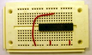
Ground Connections
Next is the power connections. I have included the ground connections we did before as this is a work in progress. I also included a 47k resistor attached to pin one (MCLR). Yes the top single row of holes is the power (VDD) and the bottom single row of holes is the ground (VSS). I will attempt to keep the power and ground consistent.
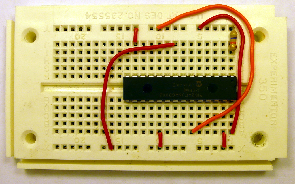
Power and Ground Connections
Now I have added the wiring necessary for the debug connector. This connector is made of two inline pins soldered together at a right angle. It is very handy for attaching a PICkit 3 which is what I used to program the microprocessor.
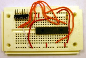
Debugging Connection
Now add the wires for the LED. You will also notice that I have added the capacitor for the regulator. I have a non-polarized cap in mine but, you can use a 10uf polarized cap without a problem just make sure you get the polarity correct. The minus leg should go to the pin that is grounded.
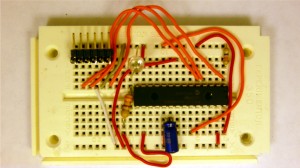
LED Connection
Here is a complete schematic of what we wired up on the breadboard.
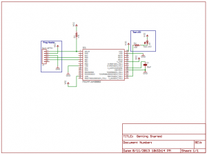
Blink LED Schematic
Blinking LED
Now that that is out of the way on with the tutorial. The library contains several module that gives the user several different functions. This document is to explain these functions.
The library may be obtained at http://theengineertutor.com/ under downloads. It does require registration but the base library can be obtained for free after the registration. Get the latest library TETSTLib_xxxxx.zip. If you want further functionality, beyond the standard library, it requires a small fee.
The library has the ability to run tasks, delay tasks, manipulate I/O pins, and run a serial port. The library gives you a good deal of flexibility in performing these tasks. The library contains a very simple RTOS that allows you to do several things at seemingly the same time. It is an event driven RTOS without preemption. I will explain this in just a moment.
Lets get to a small example. Let’s do the embedded system “Hello World” equivalent, blinking an LED. Seems everyone starts with this simple task. And, rightly so, it shows the ability to compile and program the microcontroller using your tools and that the microcontroller is running and doing what you asked it to do.
#include <p24fxxxx.h>
#include <string.h>
#include "rtos.h"
#include "pins.h"
#include "initializeSystem.h"

unsigned int on = 0;

//
/******************************************************************************
 * Function void blink(void)
 *
 * This function is called by the RTOS when the delay has expired.  Interesting
 * to note that you have to call the delay routine again to get another delay.
 * The LED is flashed in this routine.
 *
 * PreCondition:    None
 *
 * Input:           None
 *
 * Output:          None
 *
 * Side Effects:    blinks the LED and also toggles the on variable between 1 and
 *                  0.
 *
 *****************************************************************************/
void
blink(void)
{
  if (on)
  {
    digitalWrite(16,HIGH);
    on = 0;
  }
  else
  {
    digitalWrite(16,LOW);
    on = 1;
  }
  if (!delayMS(blink,500))
  {
    runNext(); // next item to be run
    // wasn't able to add to the delay queue.  It must be full.
    // Try again.
    while (!delayMS(blink,500))
      runNext();
    // or you could setup an infinite loop to catch the error in
    // a debugger.
    // while (1)
    //    ;
  }
}

/******************************************************************************
 * Function:        void main(void)
 *
 * PreCondition:    None
 *
 * Input:           None
 *
 * Output:          None
 *
 * Side Effects:    None
 *
 * Overview:        Main program entry point.
 *
 * Note:            None
 *****************************************************************************/
int main(void)
{
  initializeSystem();

  pinMode(16, OUTPUT);

  while (!delayMS(blink,500))
    runNext();

  while(1)
  {
    runNext();
  }//end while
}//end main
There it is and there is no busy waiting to toggle or blink the LED. The system in this case is idle much of the time. This allows you to put the microcontroller into a sleep mode and decrease the current draw to extend the life of a battery operated system. There are a few PIC’s that have very low current consumption in sleep mode.
Library Configuration
You will need to download the library. Next create a project in MPLAB-X for the PIC24FJ64GB002. Once you have the library downloaded unzip it in the same directory where you created your project. Now copy the above code and put it in the same directory where you created your project and call it main.c. Add main.c and config.c that came in with the library to the project under sources and the library under library. There should be several include files in with main.c and config.c. The includes should’ve come in with the unzipping of the library. Now try and build the project. It should build. If you need help with creating an MPLab-X project see here make sure you create the project for the PIC24FJ64GB002 instead of the PIC24FJ64GA002. They are different microcontrollers.
I’ll try and explain a little bit about the code and what it is doing. If we start with the main program where everything starts we find a pinMode command. This command makes pin 6 an output. Then we have a delayMS command. This command tells the RTOS to put the blink routine in the millisecond delay queue for 500 milliseconds which is .5 seconds. That means that the blink routine will be run in .5 seconds. Then we have a while(1) loop. This is the infinite loop that always runs. In this loop is a call to the runNext routine. This routine calls the RTOS and allows it to schedule the next available routine to run. A lot of times the run queue is empty. When the run queue is empty you have the opportunity to stop the processor and put it to sleep.
Now lets take a look at the blink routine. The first think the blink routine does is to see if the LED is on. If it is on it turns it off. If the LED is off it turns it on. Then the blink routine puts itself back on the delayMS queue to be run again. If you don’t put the blink routine back on the delayMS queue the blink routine won’t be run again and you won’t have a blinking LED.
Remember I mentioned that the RTOS doesn’t have preemption. That means that if you create a task that doesn’t release the CPU your task can take over the machine and nothing else gets done. You can take over the entire machine so that only interrupts are working. To avoid this problem it is best to break up long processing requirements into small chunks that run very fast. The best way to do this is through a state machine. If you need to know what a state machine is please follow this link.
The maximum delay that the delayMS routine can handle is 65535. Some of you may recognize that as a power of two. Yes, the delayMS routine uses an unsigned int for the delay. Now you are probably saying that is just over a minute (65535/1000 = 65.535 seconds to be exact). But, you can change things together to get longer delays.
You can do that with the following code in the delay routine.
#include <p24fxxxx.h>
#include <string.h>
#include "rtos.h"
#include "pins.h"
#include "initializeSystem.h"

#define TWO_MINUTE_DELAY 2
#define FIVE_MINUTE_DELAY 5
#define TEN_MINUTE_DELAY 10
#define TWENTY_MINUTE_DELAY 20
#define MINUTEDELAY 60000
// (60/(MINUTEDELAY/1000))

unsigned int on = 0;
unsigned int delayCount = TWO_MINUTE_DELAY;

//
/******************************************************************************
 * Function void blink(void)
 *
 * This function is called by the RTOS when the delay has expired.  Interesting
 * to note that you have to call the delay routine again to get another delay.
 * The LED is flashed in this routine.
 *
 * PreCondition:    None
 *
 * Input:           None
 *
 * Output:          None
 *
 * Side Effects:    blinks the LED and also toggles the on variable between 1 and
 *                  0.
 *
 *****************************************************************************/
void
blink(void)
{
   if (delayCount)
   {
      delayCount--;
      if (delayCount == 0)
      {
         delayCount = TWO_MINUTE_DELAY;

         if (on)
         {
            digitalWrite(16,HIGH);
            on = 0;
         }
         else
         {
            digitalWrite(16,LOW);
            on = 1;
         }
      }
   }
   else
   {
      delayCount = TWO_MINUTE_DELAY;
   }

   // reschedule our delay of one minute
   if (!delayMS(blink,MINUTEDELAY))
   {
      runNext(); // next item to be run
      // wasn't able to add to the delay queue.  It must be full.
      // Try again.
      while (!delayMS(blink,MINUTEDELAY))
         runNext();
      // or you could setup an infinite loop to catch the error in
      // a debugger.
      // while (1)
      //    ;
   }
}

/******************************************************************************
 * Function:        void main(void)
 *
 * PreCondition:    None
 *
 * Input:           None
 *
 * Output:          None
 *
 * Side Effects:    None
 *
 * Overview:        Main program entry point.
 *
 * Note:            None
 *****************************************************************************/
int main(void)
{
   initializeSystem();

   pinMode(16, OUTPUT);

   // sync up LED and on state
   digitalWrite(16,HIGH);
   on = 0;

   // delay one minute
   while (!delayMS(blink,MINUTEDELAY))
      runNext();

   while(1)
   {
      runNext();
   }//end while
}//end main